
-
-
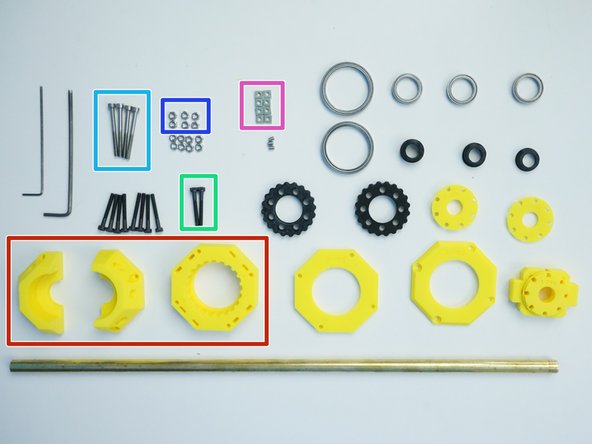
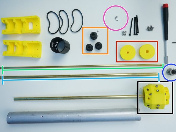
Package #4
-
Ulna Gearbox portion of Package #5
-
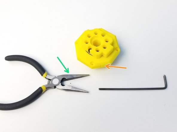
Alan Keys
-
Socket Driver [5.5mm Hex]
-
Plier
-
-
-
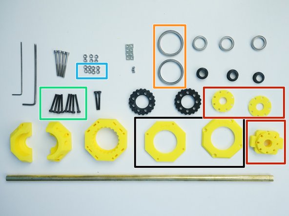
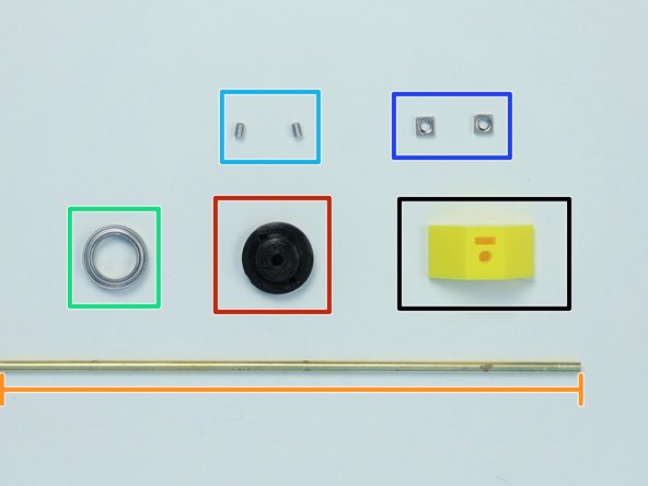
Prepare the following components:
-
[3D] - 5B Ulna GB Eccentric Cams
-
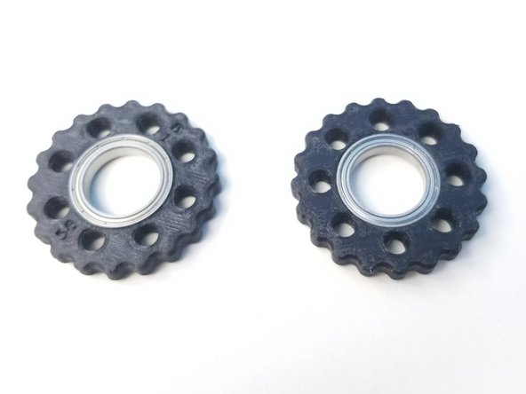
[3D] - 5B Ulna GB Rotors
-
Brass Tube [3/8'x396.35mm]
-
6702 Bearing [15x21x4mm] (x3)
-
M3x4mm Set Screw (x3)
-
-
-
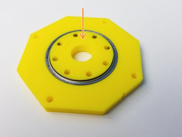
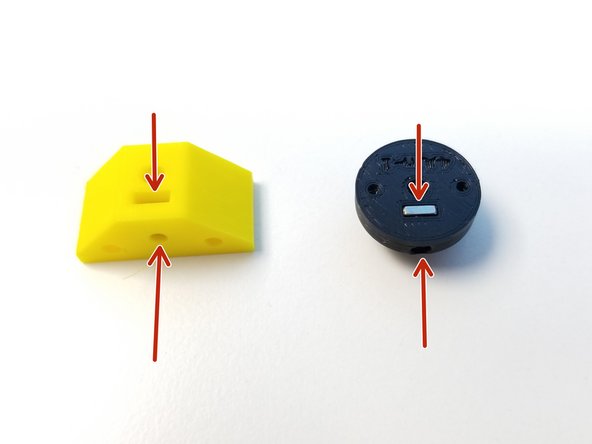
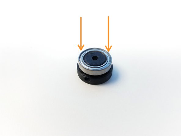
Insert the 6702 Bearings in the Rotors
-
Make sure the Bearing is all the way in.
-
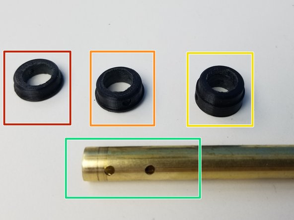
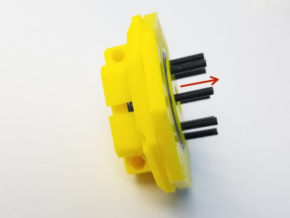
Prepare the Cams and Brass Tube that acts as the input shaft
-
Top Eccentric Cam (thinnest profile)
-
Bottom Eccentric Cam (medium profile)
-
Concentric Cam (thickest profile)
-
Machined Brass Tube, 3 hole drilled end
-
-
-
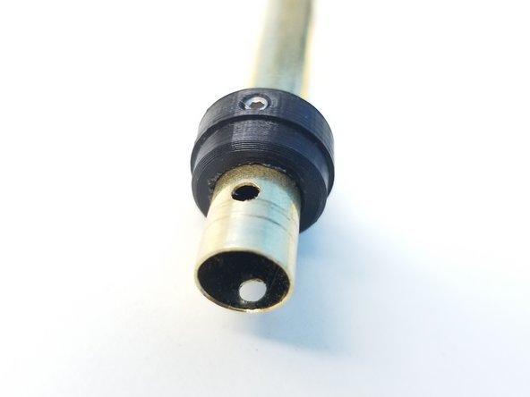
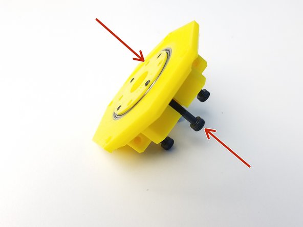
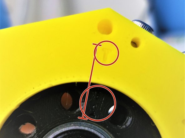
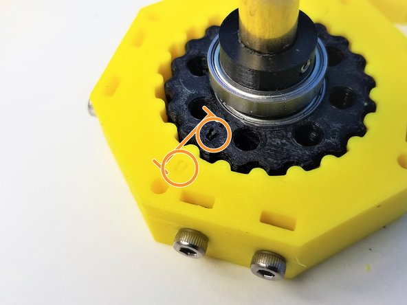
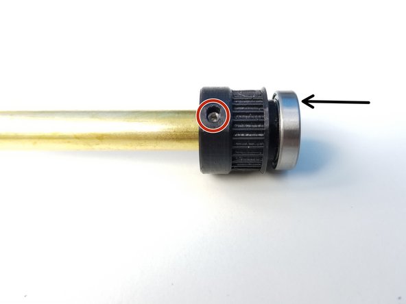
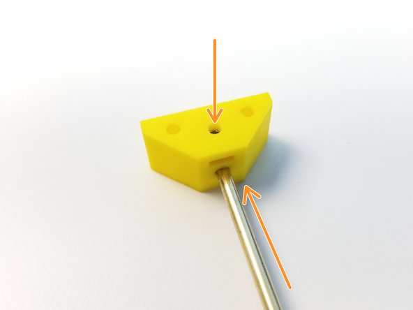
Insert and align the Concentric Cam's Set Screw hole to the furthest of 3 holes on the brass tube and secure it using a M3 Set Screw
-
Do NOT screw further than you have to. You want to make sure the screw has bit into the Brass Tube Hole but no deeper than that.
-
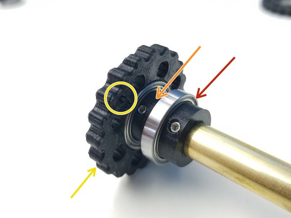
Insert the 6702 Bearing to the Concentric Cam
-
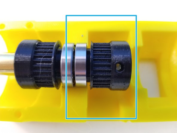
Repeat the above process with the Bottom Eccentric Cam (medium thickness)
-
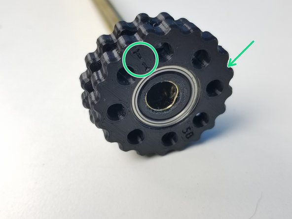
Insert the "B" Rotor, once the Set Screw is tightened just enough for the bearing to go in.
-
"B" Label side of the rotor is facing the Concentric Cam
-
Repeat the Orange and Yellow steps with the Top Eccentric Cam (thinnest profile) and "T" Rotor
-
"T" Label side of the rotor is facing away from the Concentric Cam
-
-
-
Prepare the following components:
-
[3D] - 5Bc Ulna GB Housing Tops
-
[3D] - 5Bd Ulna GB Output Disks
-
6706 Bearing [30x37x4mm] (x2)
-
M3x25mm Screws (x8)
-
M3 Hex Nuts (x8)
-
-
-
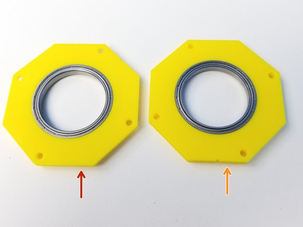
Insert 6706 Bearings into two Top Housing parts
-
Top Output Housing (chamfered on one side)
-
Bottom Output Housing (not chamfered)
-
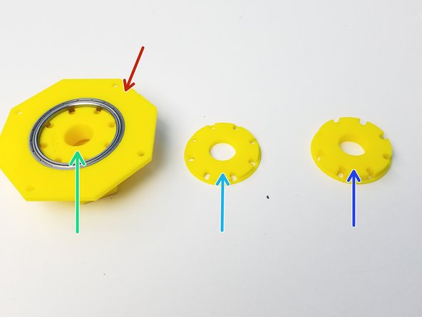
Prepare the Output Disks with the Top Output Disk inserted on the Chamfered side of the Top Output Housing
-
Top Output Disk (Thick Cross)
-
Middle Output Disk (Thinnest disk)
-
Bottom Output Disk (Medium Thickness disk)
-
-
-
Place the Middle Output Disk on the other side of the Top Output Housing
-
Use the M3x25mm Screws to hold them in place
-
Insert the Bottom Output Disk on the Bottom Output Housing
-
Make sure the label side of the Bottom Output Housing is facing down when inserting
-
-
-
Screw in the M3x25mm Screws all the way
-
Align the two Output Housings along the alignment marker
-
Use Needle Nose Pliers to tighten the M3 Hex Nuts
-
-
-
Prepare the following components:
-
[3D] - 5Ba-b Ulna GB Housing
-
M3x5mm Screws (x8)
-
M3x25mm Screws (x2)
-
M3x35mm Screws (x4)
-
M3 Hex Nuts (x6)
-
M3 Square Nuts (x8)
-
-
-
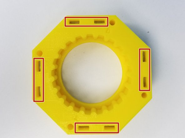
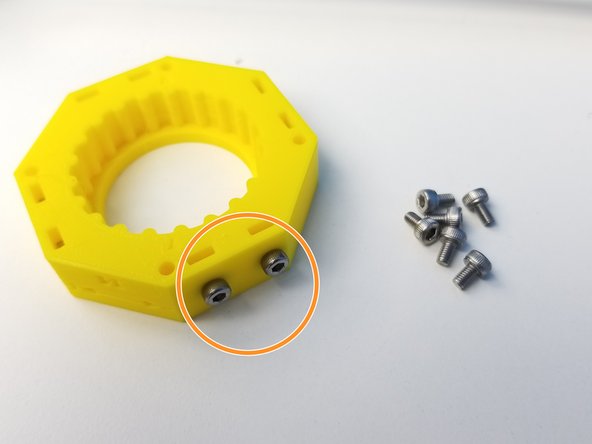
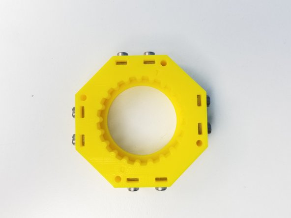
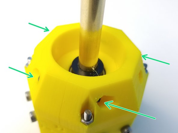
Insert M3 Square Nuts on the 5Bb Rotor Housing
-
Use M3x5mm Screws to hold these square nuts
-
These nuts are future Cable Management attachment depending on the Tool that's attached at the end effector
-
-
-
Align the "T" Labels on the rotor to the Rotor Housing and insert only the Top Rotor
-
Hard to see due to color contrast, but T on Rotor is aligned with T on the housing
-
Align the "B" Labels on the rotor to the Rotor Housing and insert it through.
-
Clamp the Bottom Housing parts on the Concentric Cam Bearing using the two M3x25mm Screws and Nuts
-
-
-
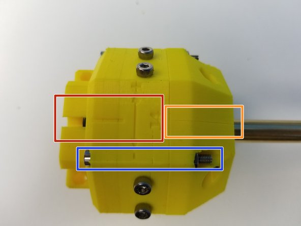
Align the Output Housing and the Rotor Housing along the alignment mark
-
Align the Bottom Housing parts in a way that the separation line is aligned to the alignment mark
-
Screw the M3x35mm Screws to secure all of the Housing components together
-
Verify that you can manually turn the eccentric shaft in the center and that the rotors smoothly turn inside the housing. Tight printing and misaligned rotors can cause the gearbox to jam.
-
-
-
Prepare the following components:
-
Assembled Ulna GB
-
[3D] - 5P Big Pulley Gears
-
[3D] - 4P Small Pulley Gears
-
Brass Tube [7/32'x494.25mm]
-
Brass Tube [5/16'x454.1mm]
-
6701 Bearings [12x18x4mm] (x5)
-
M3x4mm Set Screws (x5)
-
-
-
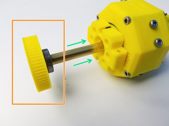
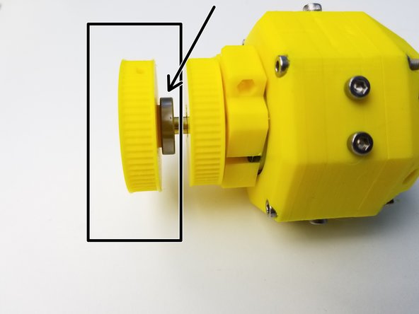
Insert 6701 Bearing on the Small 3/8' Pulley Gear and align the set screw hole to the other end of the Ulna Gearbox Shaft (3/8' Brass Tube)
-
Secure both pieces using the M3 Set Screw
-
Insert the 6701 Bearing on the Big 5/16' Pulley Gear and secure the Pulley Gear to the 5/16' Brass Tube using M3 Set Screw
-
If the Brass Tube is NOT flushed to the face of the Big Pulley Gear, then that's the wrong end of the Brass Tube
-
Insert the 5/16' Brass Tube through the Ulna Gear Box
-
Repeat the First Instruction (Black) of this step with the Small 5/16' Pulley Gear
-
Notice that the orientation of the Small 5/16' Pulley Gear is Opposite of the first step
-
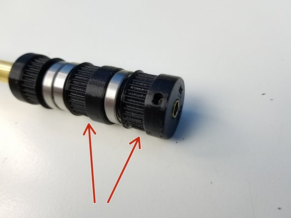
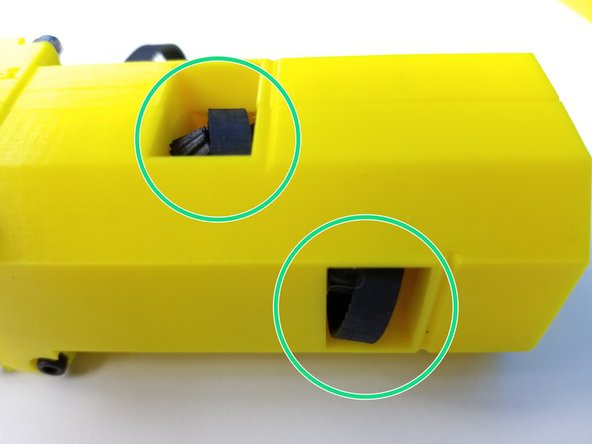
Check that when Big Pulley Gear is pushed all the in the output disk of the Ulna Gearbox, the small Pulley gear Bearings are spaced apart correctly, using one of the Tail pieces
-
-
-
Repeat Step 16 "Pulley Assemblies 1" for 7/32' Tube and Pulley Gears
-
Reminder to put the 6701 Bearings on the Pulleys before inserting the Pulleys to the Tube
-
Alignment of Small 7/32' Pulley Gear is the same as the 5/16' one, Tube should be flushed to the face of the Pulley if done correctly
-
-
-
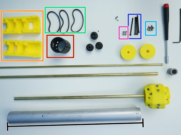
Prepare the following Components:
-
Aluminum Pipe [1.375'x360.25mm]
-
[3D] - 4S Sixi Spacer
-
[3D] - 4A Elbow Tail Housings
-
Timing Belt GT2-160mm (x3)
-
M3x10mm Screws (x4)
-
M3x45mm Screws (x4)
-
M3 Hex Nuts (x4)
-
-
-
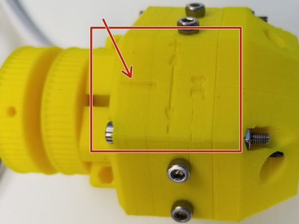
The side of the Ulna Gearbox that has the alignment line is going to be referred to as "TOP"
-
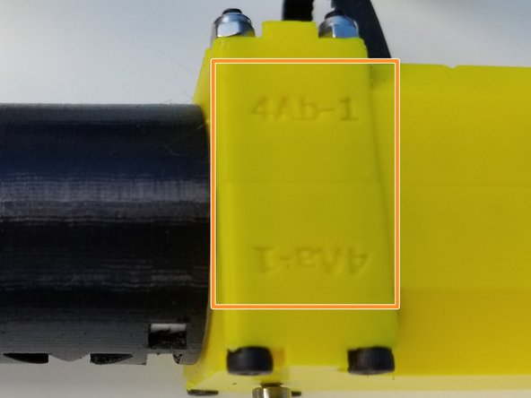
The side of the Elbow Tail Housing that has the 4A Labels is going to be referred to as "TOP"
-
-
-
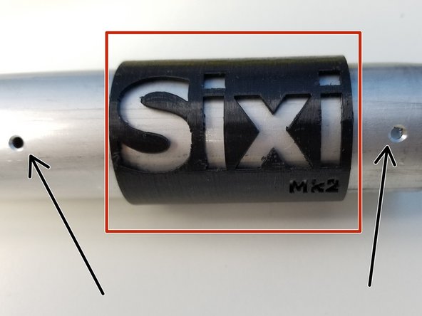
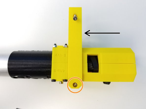
Notice that looking at it from the side, one end of the Machined Aluminum Pipe has 2 holes and the other end has 1 holes, the end with the 2 holes is the Elbow Tail End
-
Insert the Sixi Sleeve on the Aluminum Pipe between two alignment holes
-
Insert and align the 1-hole end of the Pipe into the Ulna Gearbox Housing and secure it in place with M3x10mm Screws
-
Screws on both side
-
-
-
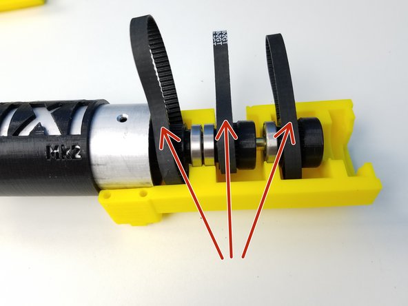
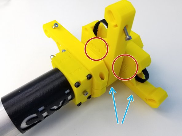
Place the GT-2 Timing Belts around the Small Pulley Gears
-
MUST PUT THE BELTS BEFORE ELBOW TAIL!
-
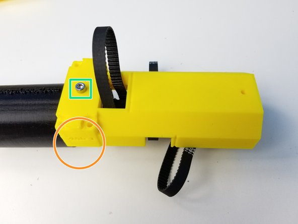
Align one of the Elbow Tail Housing's TOP side with the Ulna Gearbox 's TOP side
-
Secure it in place using M3x10mm Screw
-
Once one side of the Tail Housing is secured, secure the other half using M3x10mm Screws
-
Then clamp the two halves using M3x45mm Screws and M3 NylockNuts
-
-
-
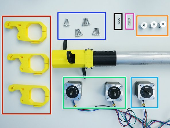
Prepare the following components:
-
[3D] - 4B Motor Mounts (x3)
-
GT2 Pulley 20t-5mm (x3)
-
NEMA17 48mm Motor (x2) Labelled Motor 3 &4
-
NEMA17 39mm Motor (x1) Labelled Motor 5
-
M3x16mm Screws (x15)
-
M3 Square Nuts (x3)
-
M3 Hex Nuts (x3)
-
-
-
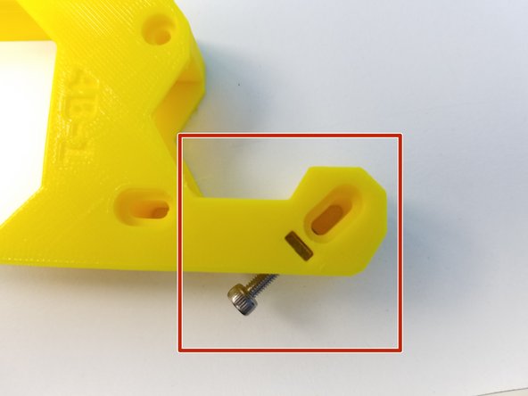
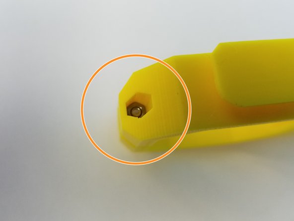
Prepare each 4B Motor Mount parts as follows:
-
Insert M3 Square Nut and secure it using M3x16mm Screw
-
Don't screw it all the way yet.
-
Insert M3 Hex Nut and secure it using M3x16mm Screw
-
Don't screw it all the way yet.
-
Fold all the GT-2 Timing Belts in the slot so it doesn't get in the way of sliding the Motor Mount through
-
-
-
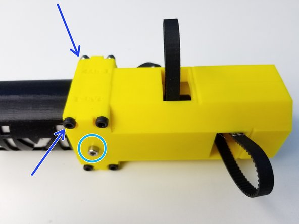
Starting with the closest slot to the SIXI Sleeve, slide and align the mount to the slot of the Elbow Tail
-
Tighten the Bottom Screw to secure it. Don't over tighten the screw.
-
Watch out for the orientation of the Mount!!Label side is facing towards the Ulna Gearbox, (see Pic3)
-
Fish out the folded GT-2 Timing Belt using the Alan Key
-
Repeat the procedures for the rest of the Motor Mount
-
-
-
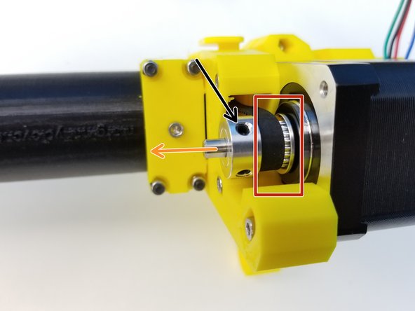
Align the GT-2 Timing Belt with the Metal Pulley
-
Check the Pulley Orientation
-
Then slide the Motor 3 shaft in the Pulley
-
Motor Cable should be facing the Elbow Tail
-
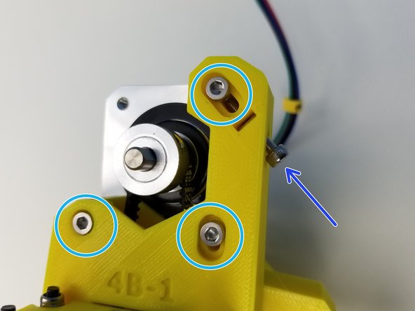
Secure Motor to the Mount by loosely screw in the M3x16mm Screws
-
Then tighten the side screw to adjust the belt tension.
-
Once the belt is tight, tighten the 3 screws.
-
-
-
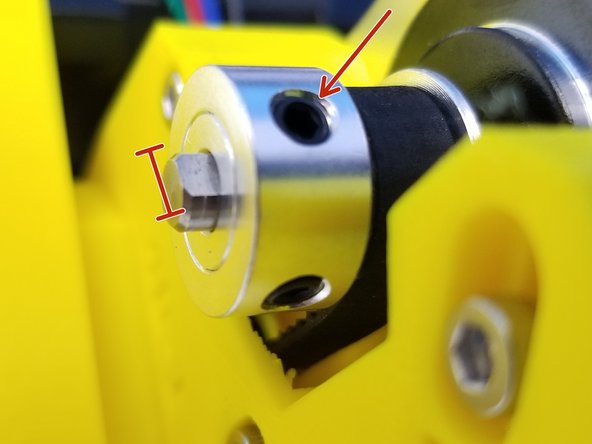
Align one of the Pulley's Set Screw to the D-Cut of the Motor Shaft. Then Secure its place by tightening both Set Screws
-
Repeat the Step 23, "Motor Mount - Mounting 2" and the above step for the rest of the motors
-
Closest to SIXI Sleeve is Motor 3
-
Middle Motor is Motor 4
-
Furthest to SIXI Sleeve is Motor 5
-
-
-
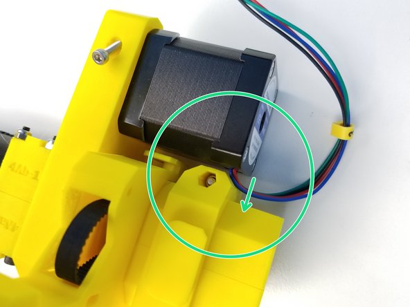
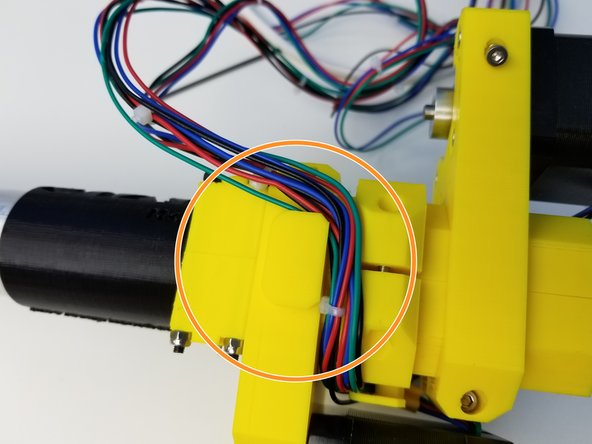
On the Motor Mount Parts, there's an extruded parts that's designed to help organize the Motor Cables
-
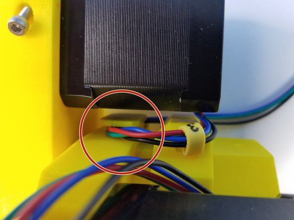
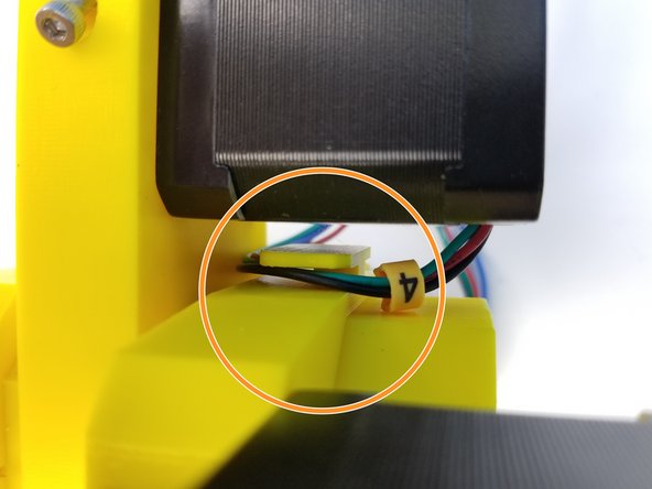
Starting with Motor 3 Cable, use the Motor 4 Mount piece to hold its cable
-
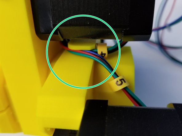
Do the same with Motor 4 Cable and use Motor 5 Mount Piece
-
Use the same Motor 5 Piece for Motor 5 Cable as well
-
-
-
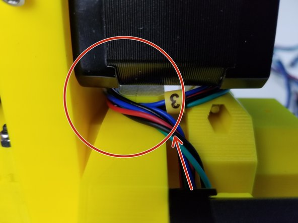
Feed the Motor 4 & Motor 5 Cables through the same opening that Motor 3 Cables went through in the last step
-
Looking from the bottom all Three Motor Cables should catch the extrusion of Motor 3 Mount piece.
-
-
-
Prepare the following components:
-
[3D] - 5Ab Ulna Rod Holder {part of Fork component}
-
[3D] - 4M Ulna Magnet Bearing {rod holder}
-
Brass Tube [1/8'x520mm]
-
6701 Bearing [12x18x4mm] (x1)
-
M3 Square Nuts (x2)
-
M3x4mm Set Screw (x2)
-
-
-
Insert M3 Square Nuts into the Brass Tube Holders and secure the Nut using the M3 Set Screws
-
Screw in just enough to secure the Square Nuts
-
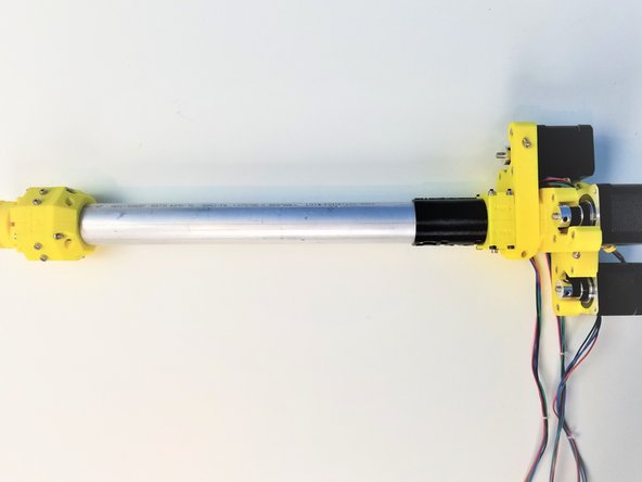
Connect the 1/8' Brass Tube to Ulna Rod Holder {5Ab} and tighten M3 Set Screw
-
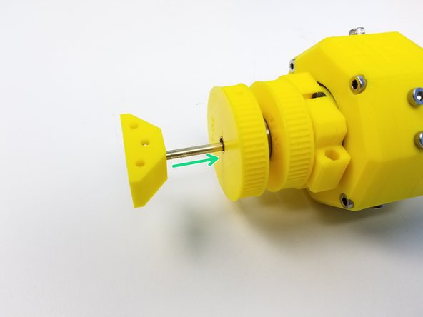
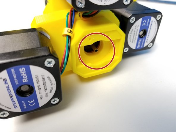
Insert the 1/8' Brass Tube through the Big Pulley Gear of the Ulna Geabox end
-
-
-
1/8' Brass Tube should stick out at the other end of the Forearm {Elbow Tail end}
-
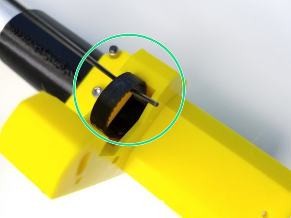
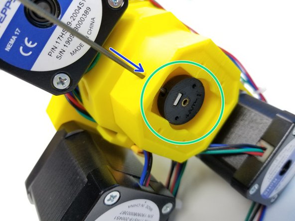
Insert 6701 Bearing to the Ulna Tube Holder {magnet end}
-
Insert the Ulna Tube Holder to the Elbow Tail and 1/8' Brass Tube
-
Secure the Brass Tube by tightening the M3 Set Screw. There's a Set Screw Tightening hole you can fit Alan Key through.
-
-
-
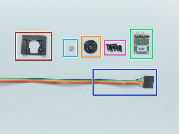
Prepare the following components:
-
[3D] - AS5147 Sensor Adapter 2
-
[3D] - 4M Ulna Magnet Holder
-
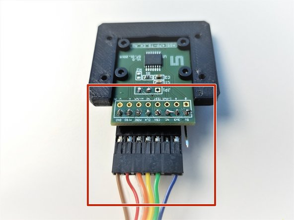
AS5147 Sensor [right angle headers on Label Side]
-
6-pin Ribbon Cable F/O - Brown to Blue {sensor 3 Ulna} - [1160mm]
-
8x2.5mm Neodymium Magnet
-
M2x6mm Screws (x10)
-
-
-
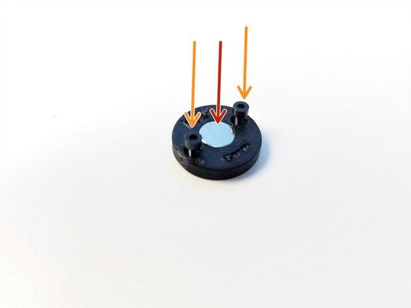
Insert Neodymium Magnet into the Magnet Holder
-
Partially screw in M2x6mm Screws in the Magnet Holder
-
Mount the Magnet Holder to the Ulna Rod Holder by tightening the M2x6mm Screws
-
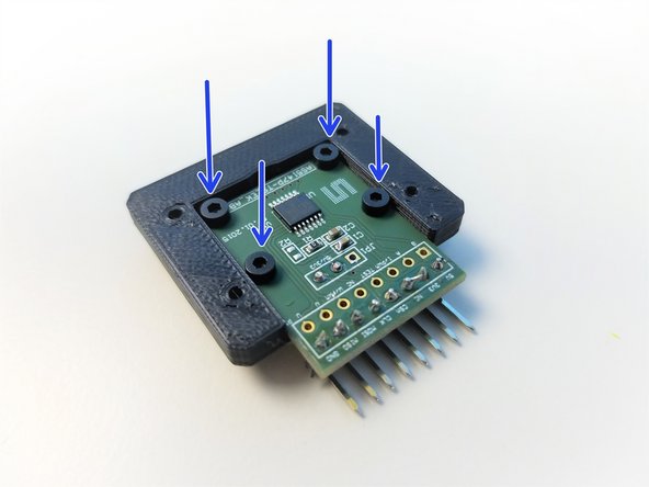
Mount the AS5147 Sensor to the Sensor Mount using the M2x6mm Screws
-
Chip is facing up
-
-
-
Connect the Sensor Cable to the AS5147 Sensor as shown in the picture
-
Blue to the 3.3V
-
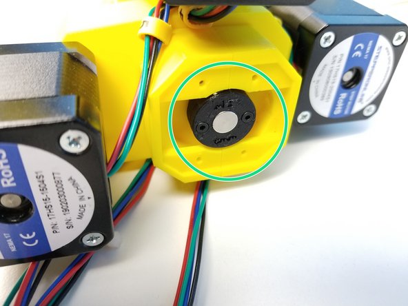
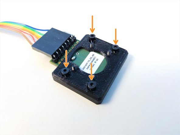
Partially screw in the M2x6mm Screws to the Sensor Mount
-
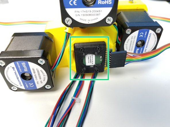
Secure the Sensor Mount to the Elbow Tail using M2x6mm Screws
-
Cable coming on the Right Side
-
-
-
Turn one of the pulleys at the motor. You should see only one of the outputs move smoothly and with no play.
-
Repeat for all three pulleys.
-


Cancel: I did not complete this guide.
One other person completed this guide.
