
-
-
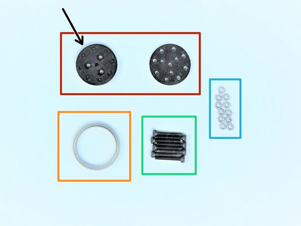
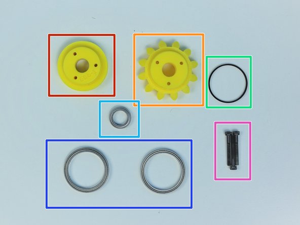
Prepare the following components:
-
[3D] - 6Da Hand GB Rotors
-
[3D] - 6Da Hand GB Eccentric Cams
-
[3D] - 6Db Hand GB Bevel Gear
-
Brass Tube [5/16' x 19.5mm]
-
6701 Bearing [12x18x4mm] (x4)
-
M3x4mm SetScrew (x3)
-
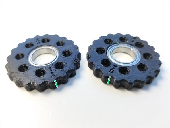
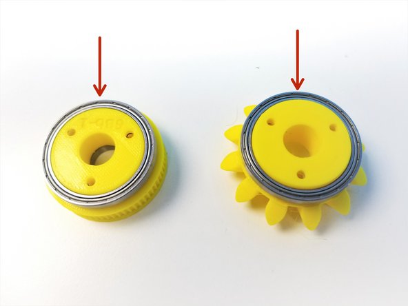
Rotors are Labelled "T" and "B" for Top and Bottom according to Eccentric Cams' Top and Bottom, Thick Piece = Bottom and Thin Piece = Top
-
-
-
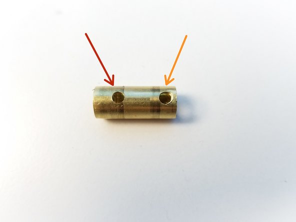
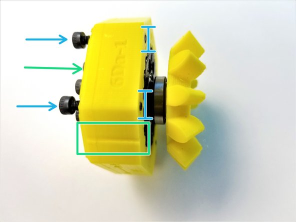
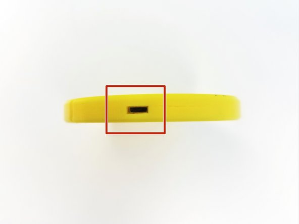
Brass Tube has one side that has 2 holes
-
Furthest away from the edge is for Bevel Gear Set Screw
-
Closest to the right edge is for Top Eccentric Cam Set Screw
-
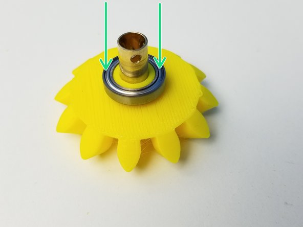
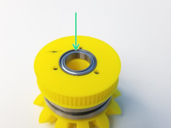
Insert 6701 Bearing in the Bevel Gear
-
-
-
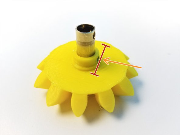
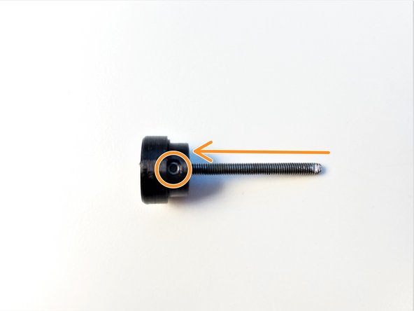
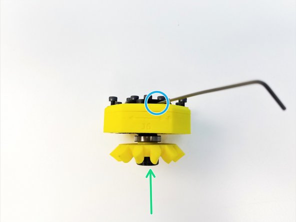
Align the Brass Tube Hole to the Bevel Gear Set Screw Hole
-
Secure the Gear using M3 Set Screw
-
Make sure the Set Screw goes in just enough for the bearing to go on, NO MORE THAN THAT
-
Slide the 6701 Bearing over the Set Screw Hole on Bevel Gear
-
-
-
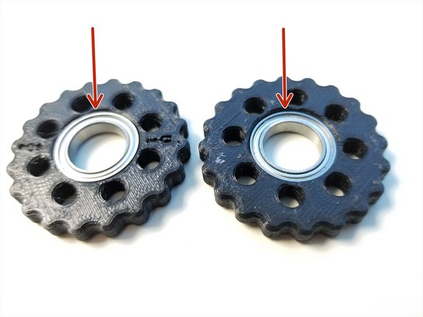
Insert 6701 Bearings into each Rotor. Make sure they are fully inserted
-
Make a sharpie mark on the side of the Rotors along the "T" and "B" label. This will help the alignment process in the future.
-
-
-
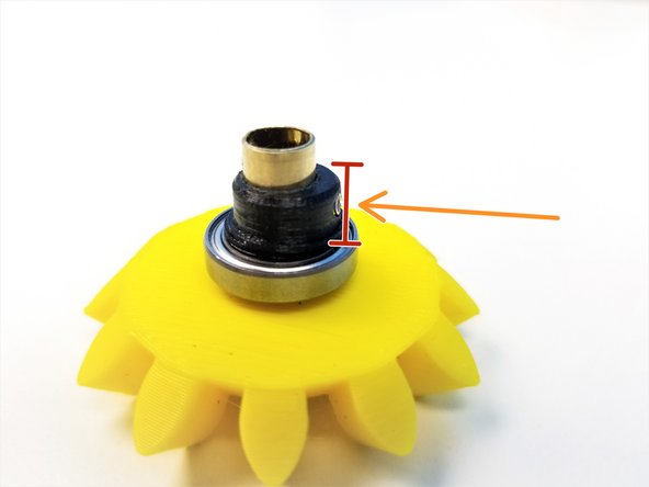
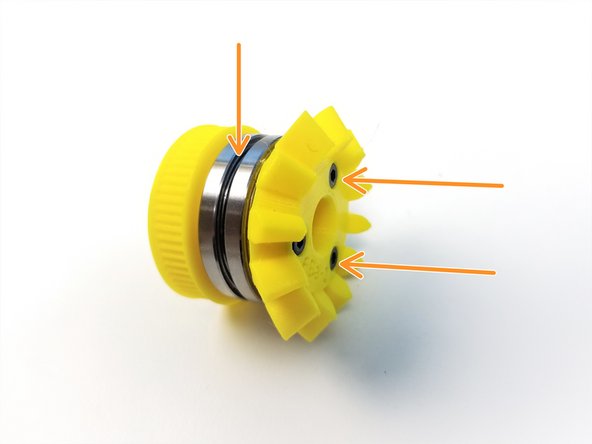
Align the Thick Eccentric Cam {Bottom} and use the M3 Set Screw to secure its location
-
Make sure the Set Screw goes in just enough for the bearing to slide over NO MORE!!
-
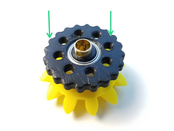
Place the "B" Rotor onto the eccentric cam with the "B" label facing the Bevel Gear
-
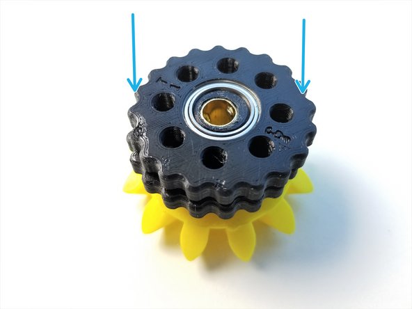
Repeat with the Thin Eccentric Cam {Top} and "T" Rotor with "T" label facing up
-
-
-
Prepare the following components:
-
[3D] - 6Da Hand GB Output Disks
-
Thicker Output Disk is considered "Top"
-
6706 Bearing [30x37x4mm] (x1)
-
M3x20mm Screws (x8)
-
M3 Hex Nuts (x11)
-
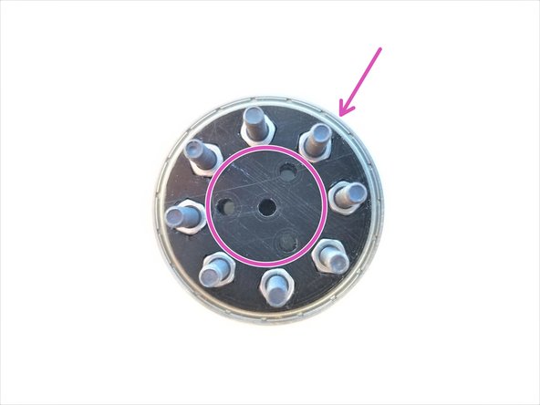
Insert M3 Hex Nuts in the nut inserts of Both Output Disks
-
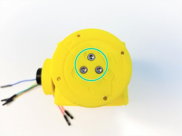
Align the 3 middle holes of Top and Bottom Disks. Clamp the 6706 bearing with the Output Disks using M3x20mm Screws
-
-
-
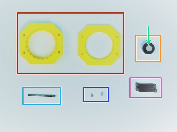
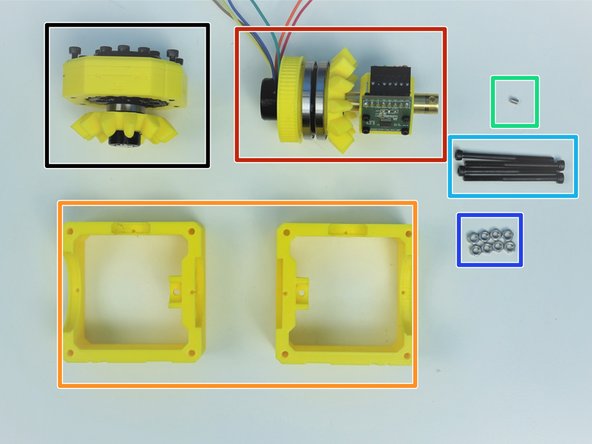
Prepare the following components:
-
[3D] - 6Da Hand GB Housing {Top & Bottom}
-
[3D] - 6Da Hand GB Magnet Holder
-
8x2.5mm Neodymium Magnet
-
M3x35mm Threaded Rod
-
Since February 2020, this is replaced with Brass Tube [1/8'x35mm]
-
M3x4mm Set Screws (x2)
-
M3x20mm Screws (x4)
-
-
-
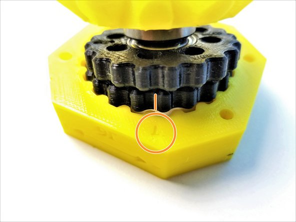
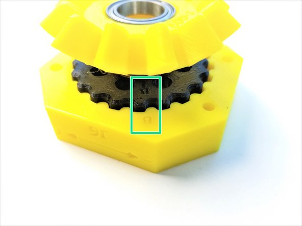
Rotor Alignment is very IMPORTANT! Follow the pictures carefully!
-
Make sure there are sharpie marks on the side of the Rotors where it lines up with "T" and "B" on the rotors
-
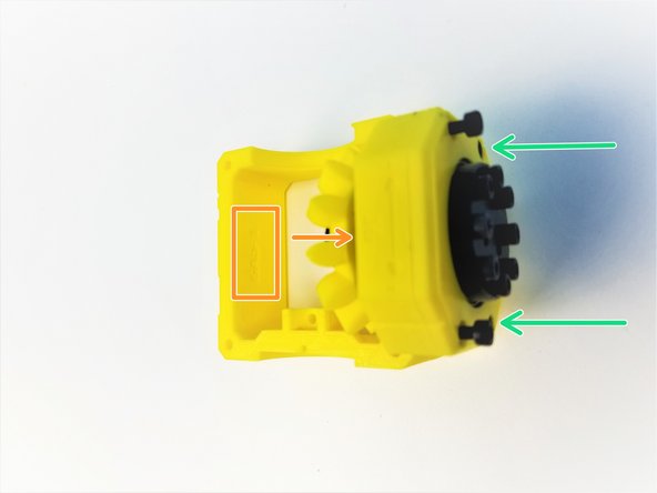
Align the Side Mark of "T" Rotor to the "T" on the Housing, and only insert Top Rotor into the housing.
-
Align the Side Mark of "B" Rotor to the "B" on the Housing, and insert the Bottom Rotor
-
When aligned properly all 8 holes made by 2 rotors intersecting should have equal spacing
-
Verify that you can manually turn the eccentric shaft in the center and that the rotors smoothly turn inside the housing. Tight printing and misaligned rotors can cause the gearbox to jam.
-
-
-
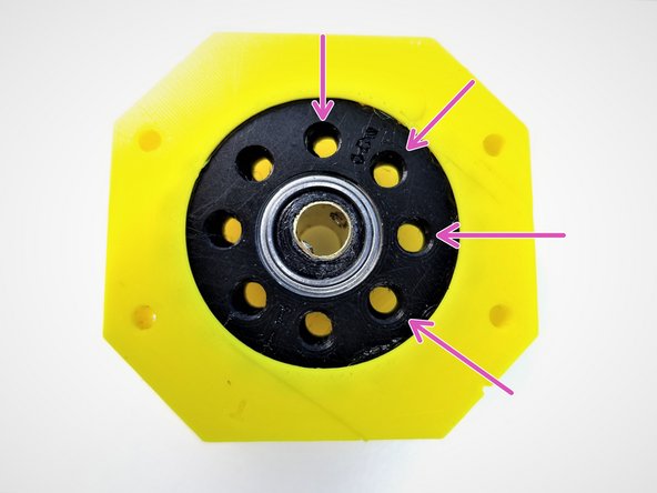
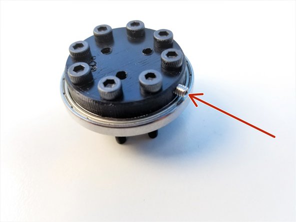
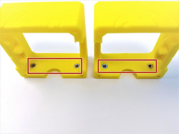
Insert M3 Set Screw on the side of the Output disk
-
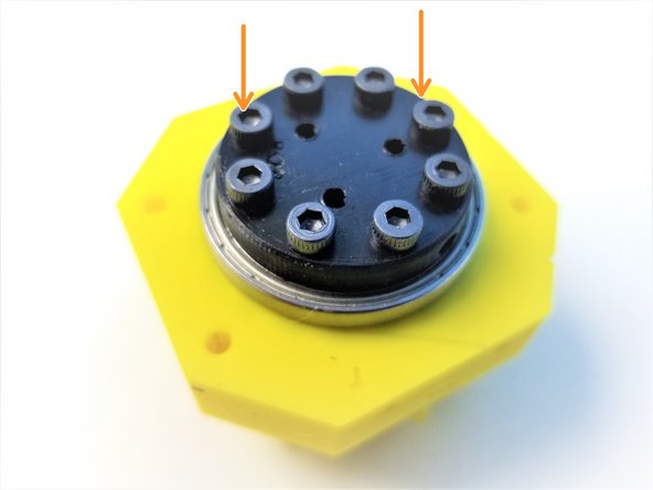
Insert the Assembled Output Disk pins through the Rotors
-
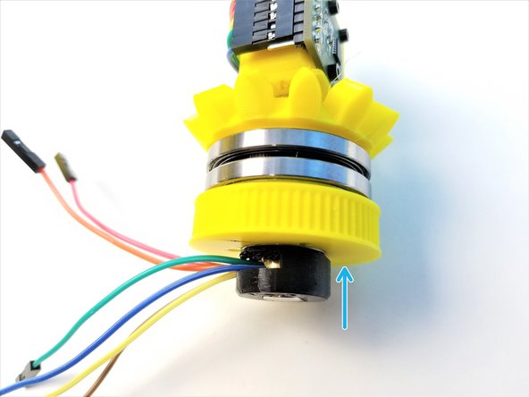
Slide in the Top Housing to 6706 Bearings on the Output Disk and align the Top & Main Housings along the alignment markers
-
Secure its position using M3x20mm Screws. ONLY screw in until it's flushed to the face of the housing
-
-
-
Insert the Neodymium Magnet in the Hand Sensor Magnet Holder, if you haven't yet.
-
Insert M3 Threaded Rod in the Magnet Holder. Secure the Rod using the M3 Set Screw
-
Feed the other end of the Rod to through the Input Shaft Tube all the way to Output Disk
-
Secure that end with a M3 Set Screw in the Output Disk
-
-
-
Prepare the following parts:
-
[3D] - 6PI Pulley Gear
-
[3D] - 6Ba Bevel Gear
-
[3D] - 6Bc Bearing Spacer
-
6701 Bearing [12x18x4mm] (x1)
-
6706 Bearing [30x37x4mm] (x2)
-
M3x25mm Screws (x3)
-
-
-
Slide in 6706 Bearings on the Pulley and Bevel Gear
-
Clamp the Bearing Spacer between the Pulley and the Bevel Gear using M3x25mm Screws
-
Insert the 6701 Bearing in the Pulley Gear
-
-
-
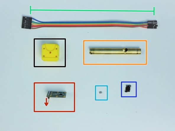
Prepare the following parts
-
[3D] - 6Ae Hand Sensor Holder
-
AS5147 Sensor {straight header on the label side}
-
Brass Tube [3/8'x76.5mm]
-
6-pin Ribbon Cable F/F - Brown to Blue {sensor 5 Hand Ext.} - [210mm]
-
M3x4mm Set Screws (x1)
-
M2x6mm Screws (x4)
-
-
-
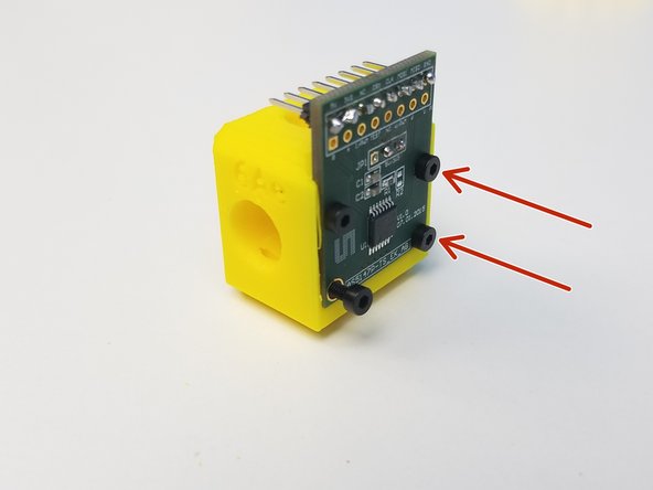
Mount the AS5147 Sensor on the Sensor Holder using the M2 Screws
-
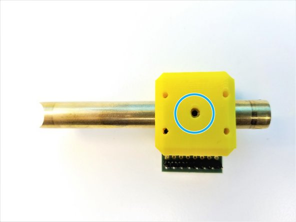
Alignment of the Brass Tube is important!!
-
Moon Cut is facing away from the Sensor Chip
-
Sensor Cable Hole is away from the Headers
-
Insert the Brass Tube through the Sensor Holder Use M3 Set Screw to secure the Sensor Holder
-
-
-
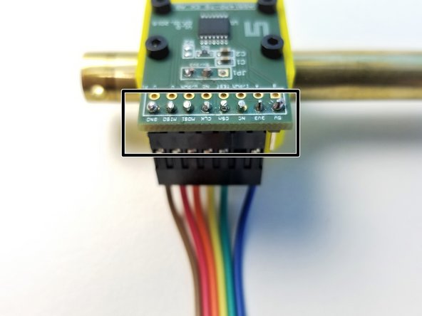
Connect the Cable to the AS5147 Sensor as shown in the picture
-
COLOR CODE MATTERS!!
-
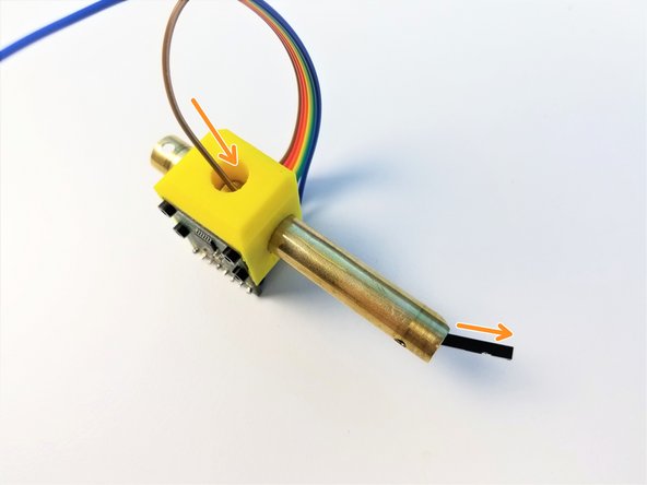
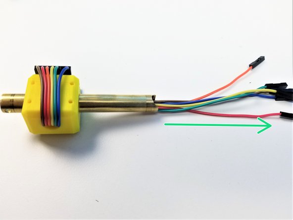
One wire at a time, feed the jumper wires through the Brass Tube
-
Make sure the Jumper Wires comes out of the Brass Tube as far as it can. NO LOOSE Cables
-
-
-
Prepare the following components:
-
Assembled Side Bevel Gear
-
Assembled Sensor Shaft
-
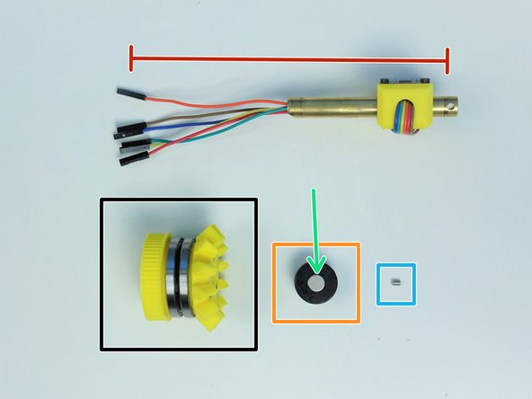
[3D] - 6Mc Picasso Magnet Holder
-
8x2.5mm Neodymium Magnet (x1)
-
M3x4mm Set Screw (x1)
-
-
-
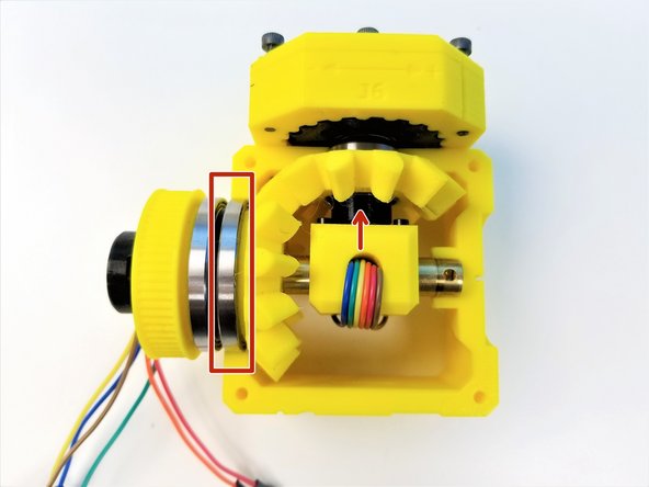
Insert the the cable end of the Brass Tube {Sensor Shaft} through the Assembled Side Bevel Gear
-
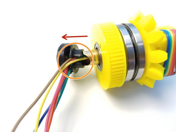
Insert Picasso Magnet Holder on the Brass Tube and align the set screw holes
-
When aligned properly, "Half Moon Cut" on the Brass Tube should line up with the opening on the Magnet Holder
-
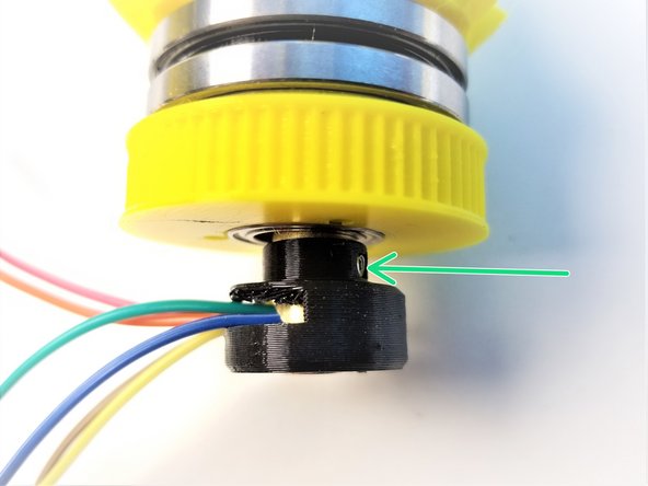
Secure the Magnet Holder using M3 Set Screw
-
Push the Magnet Holder into the 6701 Bearing that's in the Pulley Gear
-
-
-
Prepare the following components:
-
Assembled Hand Gearbox
-
Assembled Side Bevel Gearbox and Sensor Holder
-
[3D] - Picasso Box {Top = 6Aa & Bottom = 6Ab}
-
M3x4mm Set Screws (x1)
-
M3x45mm Screws (x4)
-
M3 Hex Nuts (x8)
-
-
-
Insert M3 Nuts on both Picasso Box Parts
-
Insert 6701 Bearing of the Hand Gearbox into the small bearing insert of the 6Aa Picasso Box
-
Secure the Hand Gearbox using the M3x20mm Screws
-
-
-
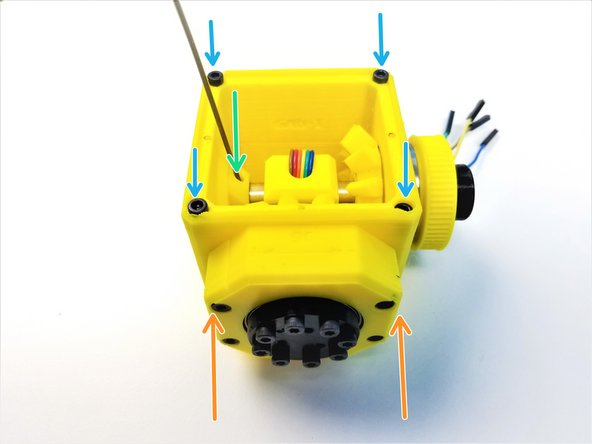
Align the 6706 Bearing closer to Bevel Gear to the Picasso bearing insert of 6Aa Picasso
-
Hand Sensor Chip should be facing the Hand Gearbox
-
Clamp the 6Ab Picasso and secure it by tightening the M3x20mm Screws on the Hand Gearbox
-
Use M3 Set Screw to secure the Sensor Shaft to the Picasso Box
-
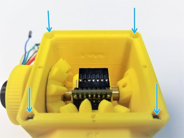
Insert M3x45mm Screws on one side and M3 Nuts on the other, to clamp the Picasso Box
-
-
-
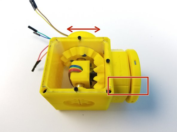
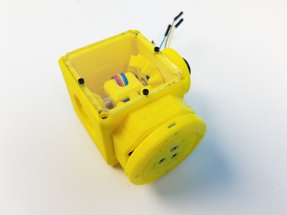
Hold the picasso box with one hand and turn the input pulley of the Side Bevel Gearbox with the other.
-
The input pulley and the hand should turn smoothly at different ratios, with little or no play.
-
If the gearbox refuses to turn, it is very likely the 3D printed gears are too tight. Now is the time to reprint them before continuing with assembly.
-
-
-
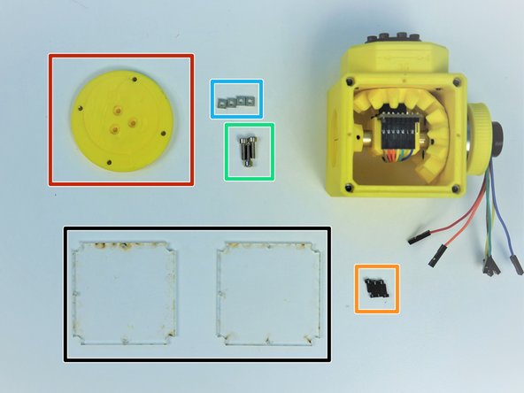
Prepare the following parts:
-
[LSR] - Acrylic Picasso Cover Plates (x2)
-
[3D] - 6Da Hand Face
-
M2x6mm Screws (x6)
-
M3x10mm Screws (x3)
-
M3 Square Nuts (x4)
-
Screw the Acrylic Plates to Top AND Bottom of Picasso Box with M2 Screws
-
-
-
Insert M3 Square Nuts on the side of the Hand Face
-
Align the Screw Hole on the ++Hand Gearbox Output and Hand Face++
-
One of three holes are in between the Screw Head
-
Secure the Face to the Output Disk using M3x10mm Screws
-
-
-
Align the Hand Face to the Hand Gearbox Housing by rotating the Pulley Gear
-
Congratulation! you have your Picasso Box assembled!!!
-


![[3D] - 6Da Hand GB Rotors](https://d3t0tbmlie281e.cloudfront.net/igi/mcr/n3COSDCEKQAQoyay.medium)


![[3D] - 6Da Hand GB Output Disks](https://d3t0tbmlie281e.cloudfront.net/igi/mcr/Cet3v2ALMRJe34OT.medium)


![[LSR] - Acrylic Picasso Cover Plates (x2)](https://d3t0tbmlie281e.cloudfront.net/igi/mcr/VGwVcvnvAJBplXtL.medium)

Cancel: I did not complete this guide.
One other person completed this guide.
