
-
-
Tools required for assembling SIXI:
-
Alan Keys (metric): Ball End is recommended
-
5mm Hex Nut Driver
-
Needle Nose Plier
-
-
-
Most 3D printed parts are labelled to verify the package and versions.
-
-
-
Read each chapter before you start work. Catch confusing things early!
-
Always follow every step in order.
-
If a step is unclear, use the comment section below it to let us know.
-
Steps may be color coded and have matching colored symbols on the pictures. A single picture could have more than one symbol.
-
-
-
If you are 3D printing parts yourself, make sure to calibrate your printer! Bad tolerances will make gearboxes either (A) sloppy or (B) so tight they don't move.
-
-
-
[3D] Electronic Case Package
-
Robot Electronics
-
Alan Keys
-
Flat Screw Driver
-
Needle Nose Pliers
-
Multimeter
-
Ferrule Crimper (optional)
-
-
-
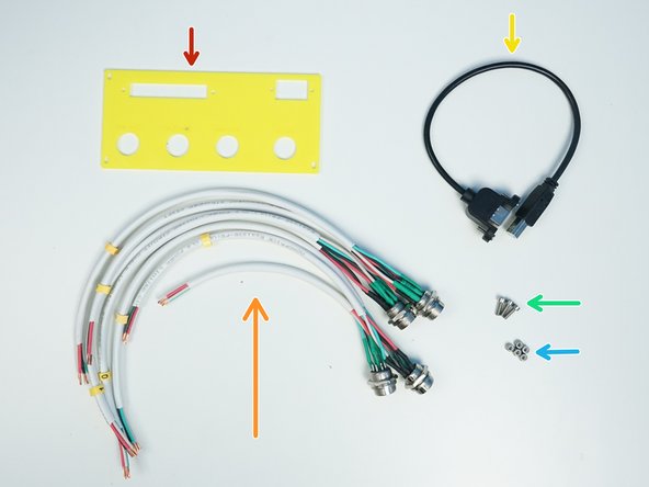
Prepare the following components:
-
ABS Junction Box {380x260x105mm}
-
[3D] - 7E-plug wall adapter
-
Aviation GX16-8p Cable M/O (wire assembled and numbered)
-
USB-B M/F Panel Mount Extension
-
M3x10mm Screws (x3)
-
M3 Nylock Nuts (x5)
-
-
-
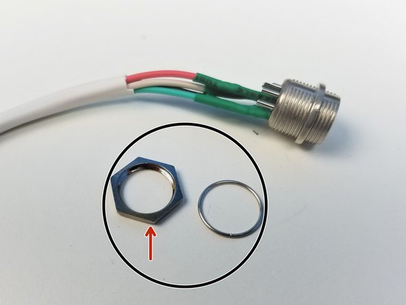
Unscrew the Wall Mount Nuts from each connectors
-
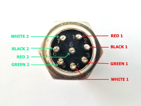
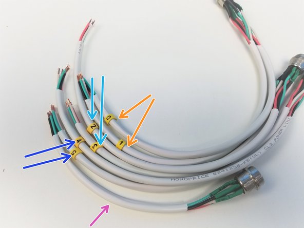
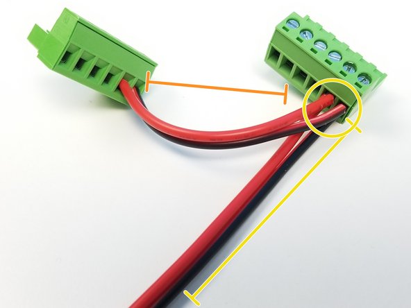
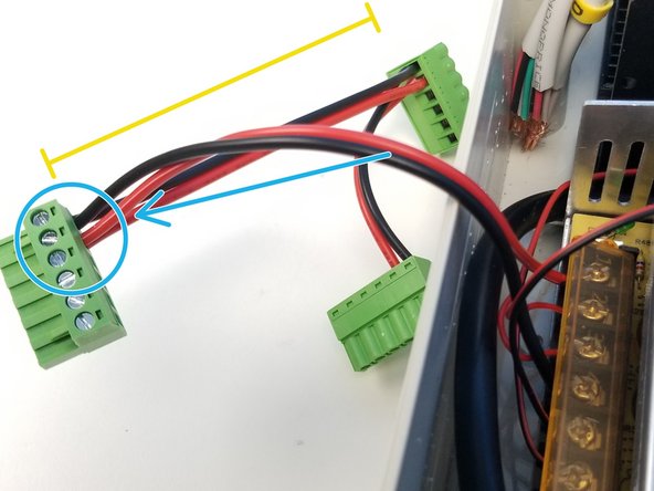
Each Connectors have 2 sets of 4pin wires soldered in this specific manner
-
The wires are cut to length as follows:
-
0 & 1 = 370mm & 370mm respectively
-
2 & 3 = 370mm & 270mm respectively
-
4 & 5 = 340mm & 310mm respectively
-
Not Labelled = Tool --> 190mm
-
-
-
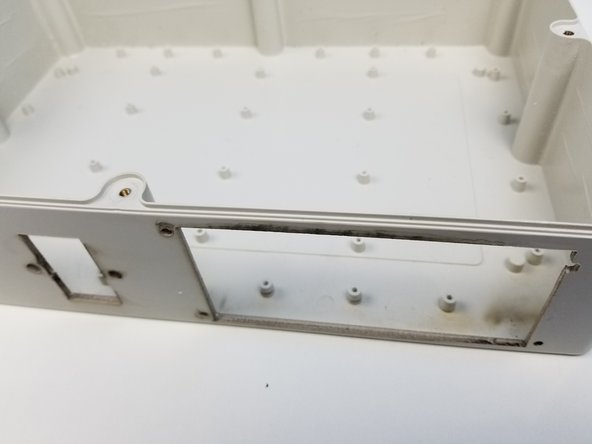
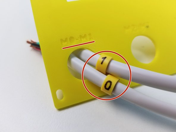
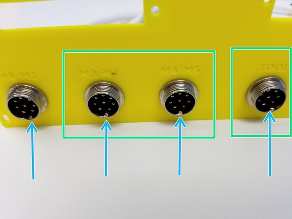
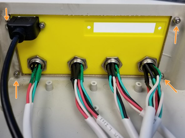
Familiarize yourself with the panel. The back side has a lip and the front side is labelled with each connector.
-
Feed the Cables through the Wall Adapter as labelled. Make sure the long end of the cable ends up on the back side of the panel.
-
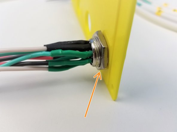
Tighten the Mounting Nut that was unscrewed from the previous step
-
Repeat the same process with the rest of the connectors
-
Be sure the alignment mark on the plug to be in the bottom center
-
-
-
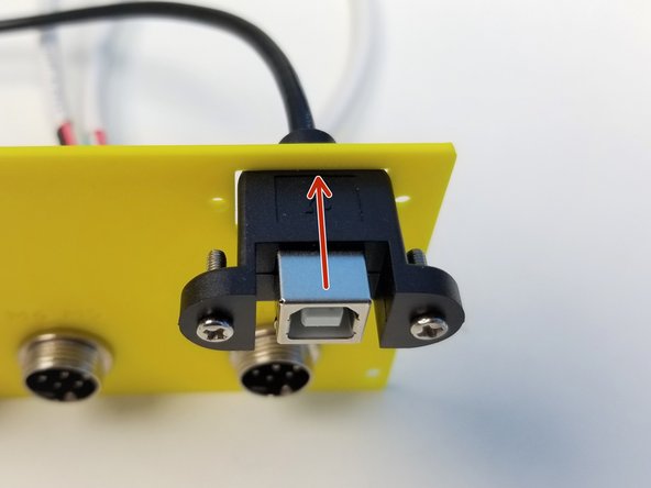
USB Extension Cable comes with M3x10mm Philip Head Screws
-
Feed the USB Cable through the Case Wall Adapter
-
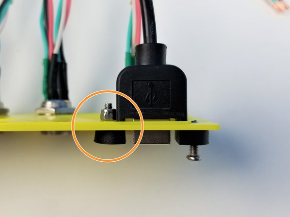
Use M3 Nylock Nut to secure USB Extension Cable in place
-
Only tighten the side furthest from the edge
-
-
-
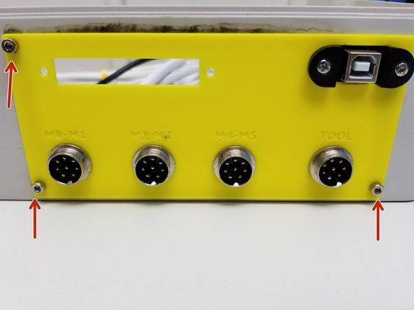
Insert the Case Wall Adapter into the Case and secure its place using the M3x10mm Screws.
-
Use the M3 Nylock Nuts on the inside of the case but don't tighten it too much. Case wall Adapter should be able to slide along the wall
-
-
-
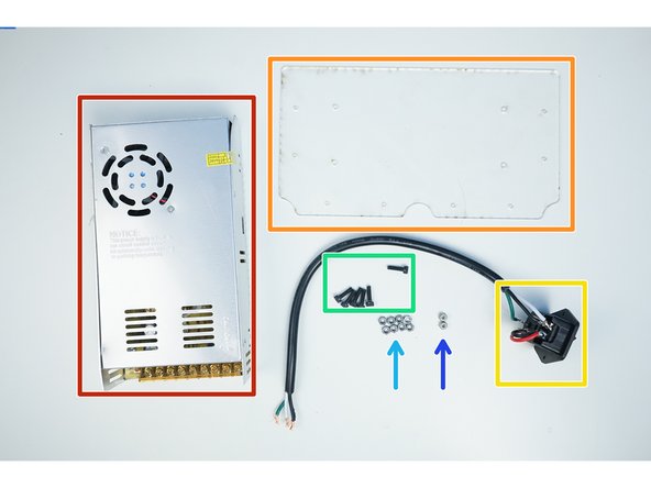
Prepare the following components:
-
Power Supply 24V-20A
-
Acrylic PSU Mounting Plate
-
Rocker Switch
-
M4x14mm Screws (x6)
-
M4 Hex Nuts (x8)
-
M4 Nylock Nuts (x2)
-
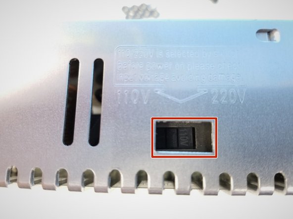
Make sure the Power Supply is set to the correct voltage, in Canada, we use 110V
-
-
-
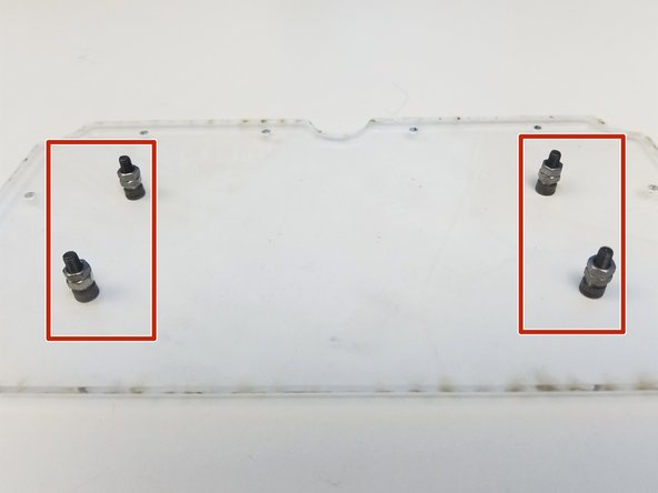
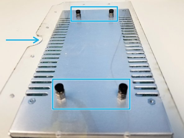
Use two M4 Hex nuts per M4x14mm Screws as spacer on the Acrylic Mounting Plate
-
Align the PSU and the Acrylic Mounting Plate as shown in the figure exactly
-
Take a closer look on the Screw Terminal of PSU
-
Take a closer look on the "Half Moon" cut on the Plate
-
Flip the Acrylic Mounting Plate on to the PSU
-
DON'T tighten 1 screw all the way at a time, this will cause the plate to flex and cause it break
-
-
-
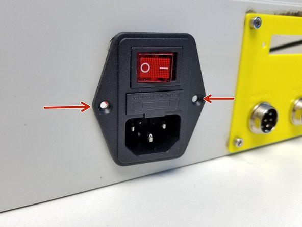
Insert the Rocker Switch into the Machined Case.
-
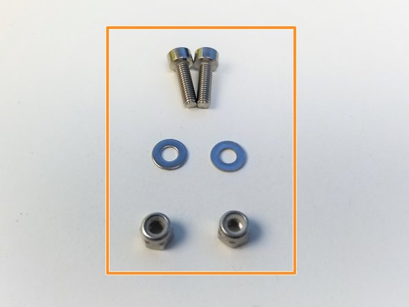
Some version of Rocker Switch has smaller mounting holes
-
if this is the case, use the M3x10mm Screws, Washers and Nylock Nuts
-
If not, use M4x14mm Screws and M4 Nylock Nuts
-
Secure the Rocker Switch with the fasteners
-
Notice the Soldering Patterns AND Length
-
18AWG Power Wires 65mm long
-
3 Wire Power Cable 365mm long
-
-
-
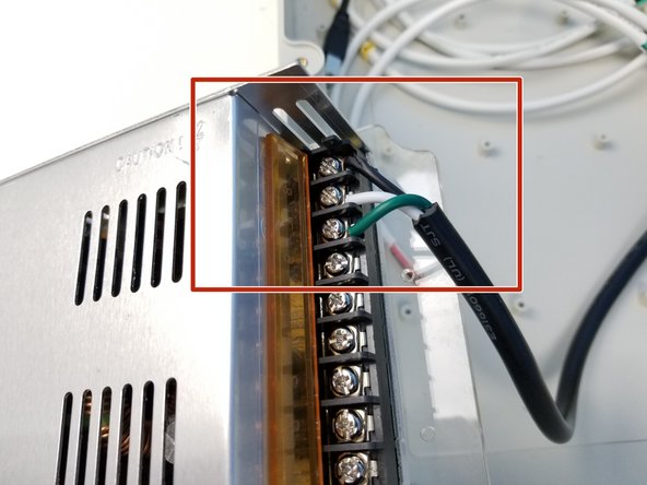
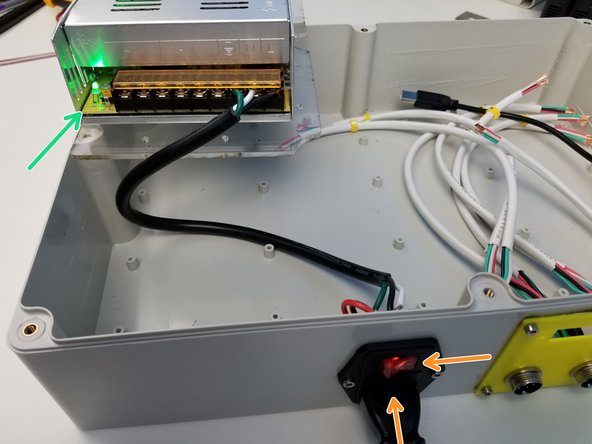
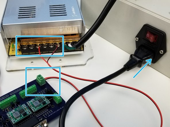
Secure the Power Cable to the PSU Screw Terminals
-
Test the Rocker Switch and PSU by connecting the Power Plug and turning the Switch ON
-
Be careful to NOT touch the screw terminals with your bare hands.
-
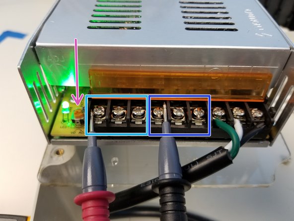
If the Green LED light turns on, it's a good sign
-
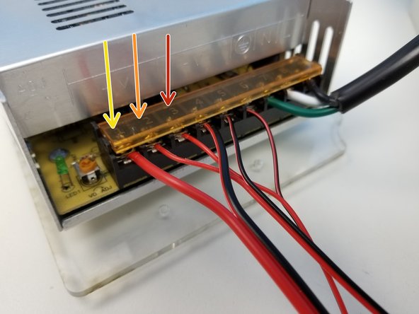
Use the Multimeter to make sure the output voltage is approximately 24V, adjust using the Philip Head Screw
-
Left 3 terminals are Positive Output
-
Middle 3 terminals are Ground/Negative Output
-
Once test is successful, Turn off the Power using the Switch and unplug the Power Plug
-
-
-
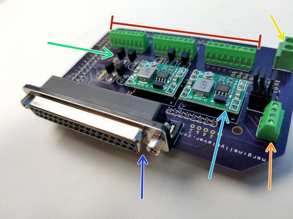
This custom Arduino Mega Shield can be ordered directly and contains the following parts:
-
Screw Terminal 8p - 2.54mm (x3)
-
Screw Terminal 4p - 2.54mm (x1)
-
Screw Terminal 2p - 3.5mm (x1)
-
NPN Transistor 2N2222A (x6-9)
-
Voltage Regulator MP1584EN (x2)
-
D-SUB F-Conn right-angle 37p
-
The voltages in the MP1584EN must be adjusted before we connect this to the Arduino Mega. Incorrect voltage could damage the electronics.
-
-
-
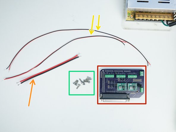
Prepare the following components:
-
Arduino Mega Shield
-
2-Wire Power Cable 18AWG - [160mm]
-
2-Wire Power Cable 22AWG - [335mm & 420mm]
-
M3x8mm Screws (x8)
-
Connect the PSU and Mega Shield using the 22AWG 420mm long wires. Connect the plug to the Switch and turn the power ON
-
Test the LEFT MP1584EN output voltage to be 6V or whichever voltage your gripper servo needs, adjust using the potentiometer
-
Test the RIGHT MP1584EN output voltage to be 10 -12V for powering Arduino Mega .
-
-
-
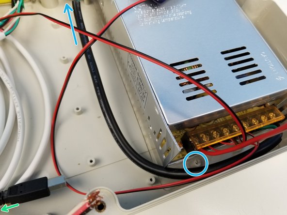
Connect the rest of the power Wires
-
Small Stepper Driver Wires (22AWG 335mm long)
-
Big Stepper Driver Wires (18AWG 160mm long)
-
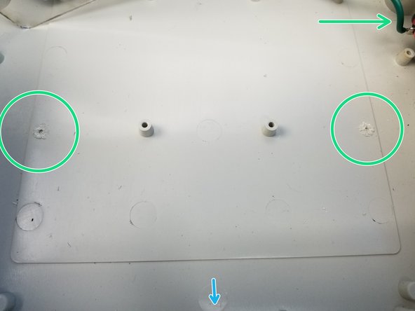
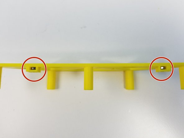
Using a wire cutter to snip two pegs positioned with respect to the Rocker Switch on the top right corner of the picture.
-
Align the Half Moon slot and secure the mounting plate to the Case using M3x8mm Screws in the available spots around PSU.
-
-
-
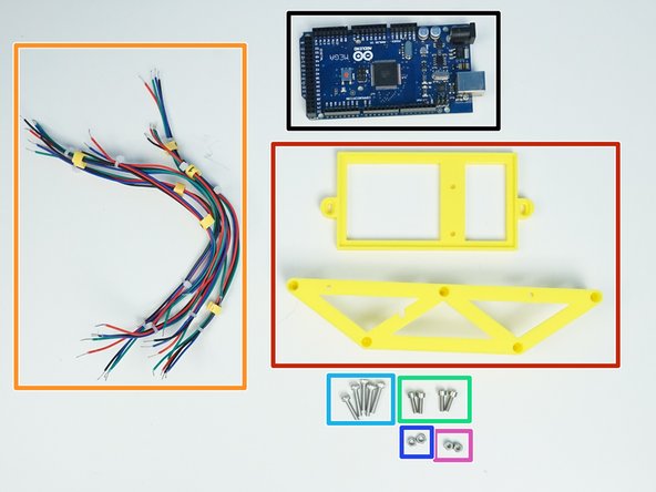
Prepare the following components:
-
Arduino Mega 2650
-
[3D] Arduino Tray and Standoffs
-
4-Wire Signal Cable 22AWG {for Motor}
-
M3x10mm Screws (x4)
-
M3x16mm Screws (x5)
-
M3 Hex Nuts (x2)
-
M3 Nylock Nuts (x2)
-
-
-
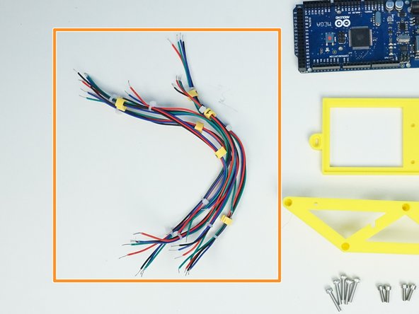
Length of each 4-pin 22AWG wires are listed as below:
-
0 -> 210mm
-
1 -> 210mm
-
2 -> 200mm
-
3 -> 165mm
-
4 -> 185mm
-
5 -> 225mm
-
-
-
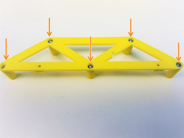
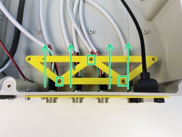
Insert M3 Hex Nuts in the side slot of the Arduino Standoff
-
Partially screw in M3x16mm Screws for easier assembly
-
Secure the Standoff to the Case by tightening the Screws in place.
-
Notice the Orientation of the Standoff as well as the position of the cables relative to the pegs of the Standoff
-
-
-
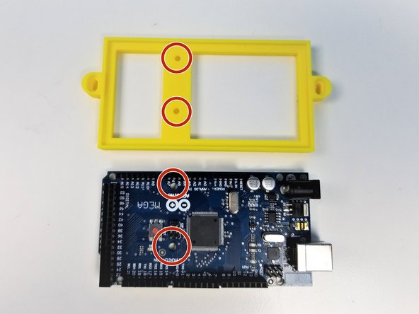
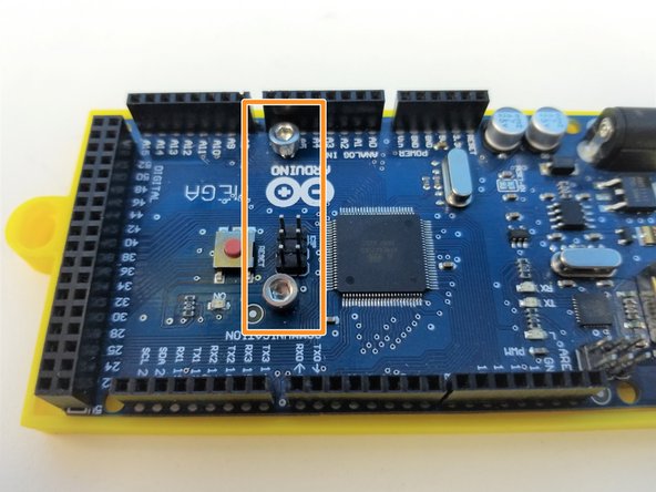
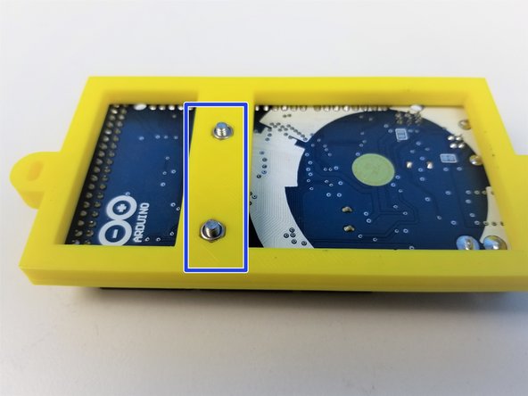
Align the Holes on the Tray and the Arduino Mega
-
Use the M3x10mm Screws and M3 Nylock Nuts to secure the Arduino to the Tray
-
Make sure to tighten the screws just enough to hold them together, No more, since over-tightening the screws can damage the board.
-
-
-
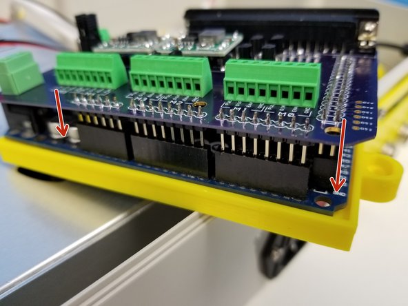
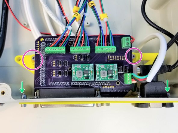
Insert the Mega Shield to the Arduino Mega
-
Make sure you have set the voltage regulator in Step 11 before going forward
-
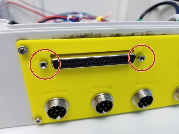
Remove the hex head screw from the Right Angle D-Sub Connector
-
-
-
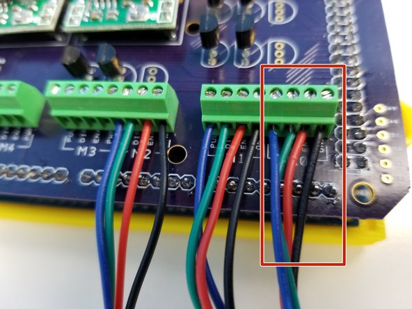
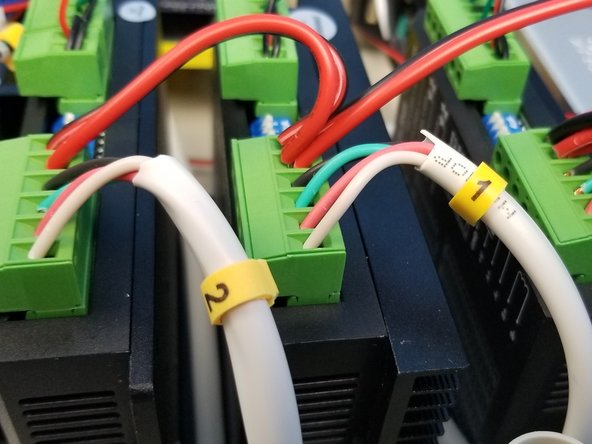
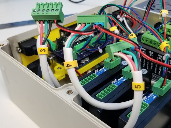
Start with Motor 0 signal cable to the Right most connector labelled "M0"
-
M0, M1 and M2 follows the same color pattern
-
from the right, Black, Red, Green, Blue
-
M3, M4, M5 follows a different color pattern from M0-M2,
-
from the right, Red, Black, Green, Blue
-
-
-
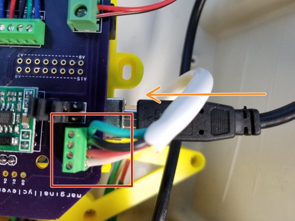
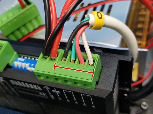
Insert the "TOOL" Cable in the specific order:
-
from the top, Green, Black, Red, White
-
Insert the USB Extension Cable in the Arduino
-
-
-
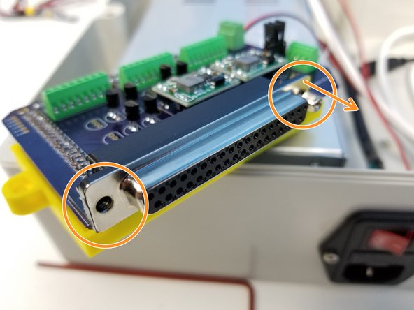
Secure the Right Angle D-Sub Connector to the Case Wall Adapter slot using the Hex Head Screws
-
Align the Tray to the Standoff and secure it using the M3x10mm Screws
-
Once everything is aligned, secure this alignment by tightening the screw and the nut on the Case Wall Adapter
-
-
-
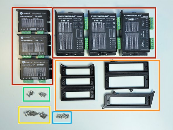
Prepare the following components:
-
Stepper Drivers [DM320T & DM542T & DM556T]
-
[3D] Stepper Driver Adapters
-
M3x10mm Screws (x12)
-
M3x8mm Screws (x9)
-
M3 Nylock Nuts (x12)
-
-
-
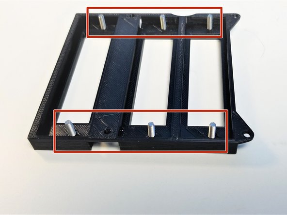
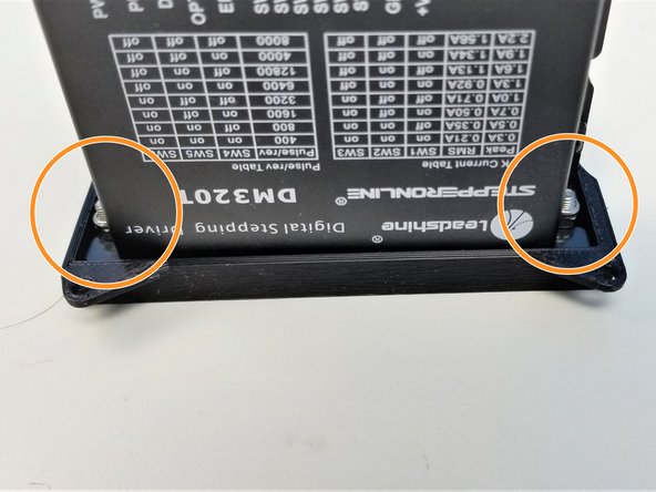
Starting with the Smaller "DM320T" Drivers, screw in M3x10mm Screws in the Adapter with 3 small slots
-
One driver at a time, secure the drivers to the adapter using M3 Nylock Nuts, use Needle Nose Plier to hold the nuts.
-
Repeat the process for the rest of the DM320T Drivers
-
-
-
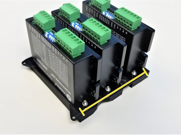
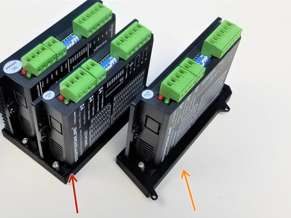
There are two DM542T Drivers and one DM556T Driver, DM556T Driver is the one with a big Heat Sink in the back
-
Repeat the same process as previous step:
-
Adapter with 2 Slots, fits each DM542T and DM556T
-
Adapter with a single slot fits one DM542T Driver
-
-
-
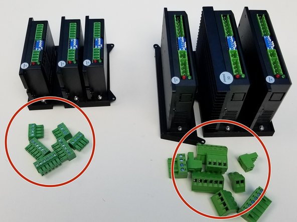
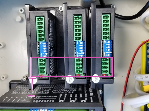
Pull all the Screw Terminal Blocks off from the Drivers
-
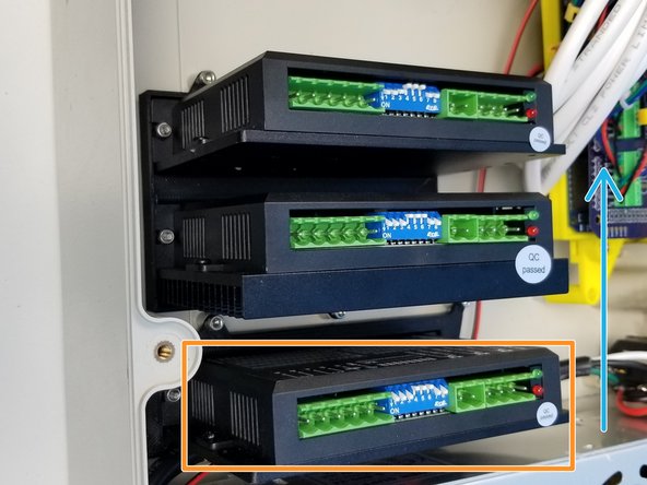
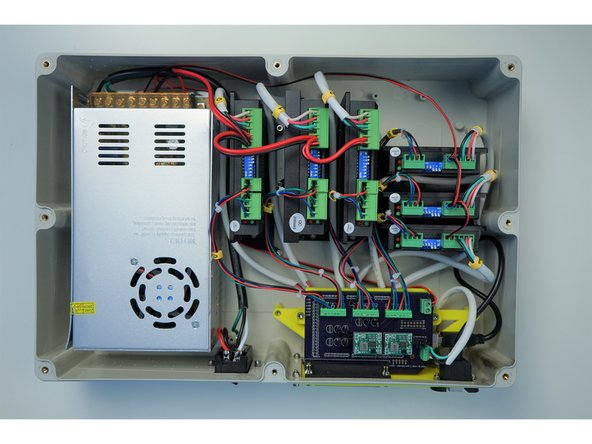
Starting with a single DM542T Driver Adapter, secure each drivers to the Case
-
Make sure the adapters are aligned as shown in the picture, Label on the DM542T and DM556T Drivers are facing away from the PSU
-
For DM320T Drivers, 4 pin side is closer to the Label of DM542T Driver
-
-
-
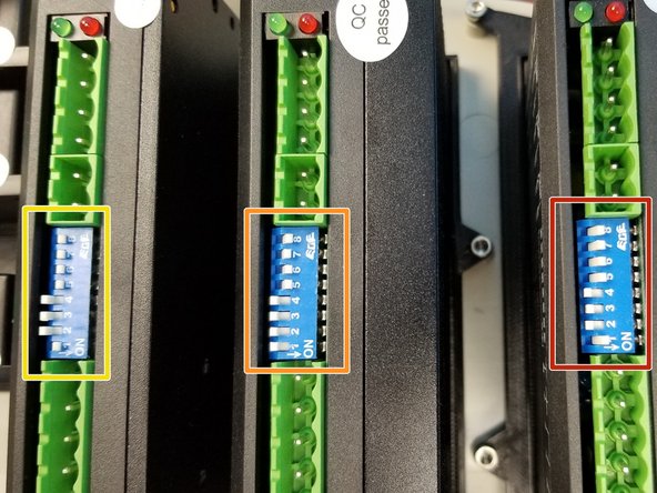
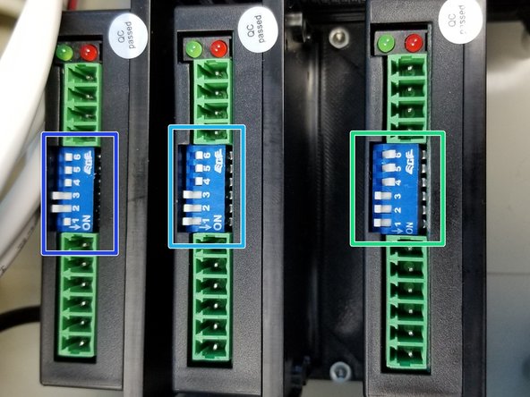
Set the switch to the following mode, it'll follow the Binary scheme, 1 = On, 0 = Off, starting from switch 1 in ascending order
-
DM542T -> 10001111
-
DM556T -> 00001111
-
DM542T -> 10001111
-
DM320T-Right -> 000111
-
DM320T-Middle -> 000111
-
DM320T- Left -> 100111
-
-
-
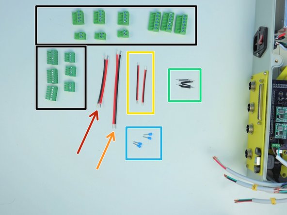
Prepare the following components:
-
Screw Terminal Blocks from the Drivers
-
2-pin Power Wires 18AWG 90mm
-
2 pin Power Wires 18AWG 130mm
-
2 pin Power Wires 22AWG 65mm (x2)
-
22 AWG solid Wires Black 30mm (x6)
-
[Opt] - Ferrule Crimp Pins (x4)
-
-
-
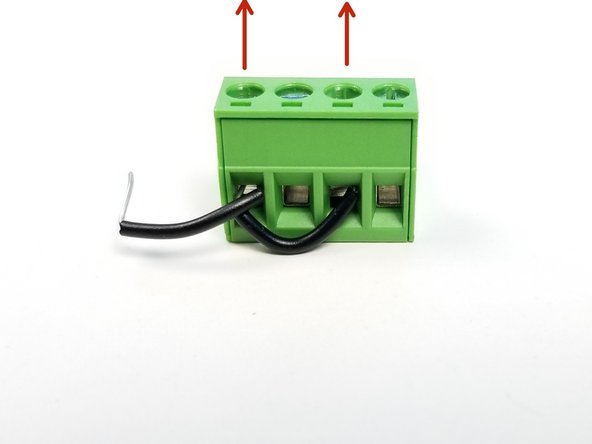
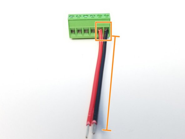
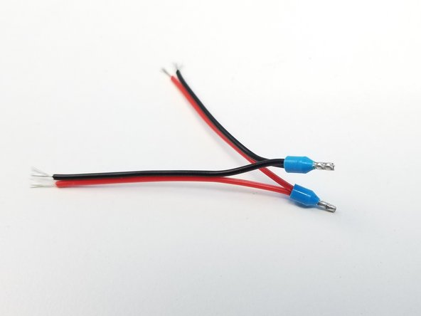
Grab one of the Bigger Driver's 4-pin Screw Terminal and wire it as shown in the first picture, Screw Head is pointing UP
-
Starting with M0 Cables that's already attached to Arduino Mega Shield, secure the wire as shown in the second picture.
-
notice there are 2 black solid wires in the right most pin of the 2-pin connector
-
Repeat the same process for the M1 and M2 Drivers, and plug them as shown in the third picture.
-
-
-
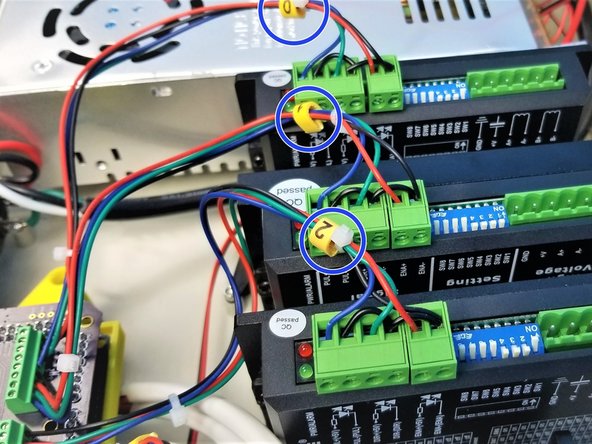
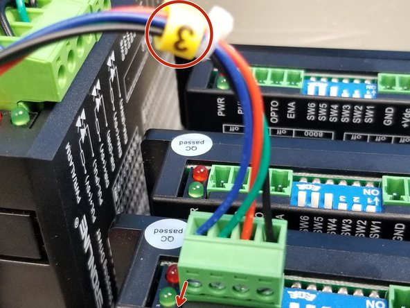
Starting with the M3 signal cable, attach them and plug them in the corresponding driver as shown in the first picture,
-
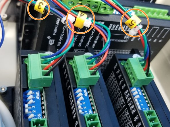
Repeat the process for M4 and M5 drivers, notice the labels
-
-
-
Use the shorter 18AWG 2-pin power cable and attach it to big 6-pin screw terminal
-
Attach the other end of the shorter 18AWG cable and one end of the longer 18AWG to another 6-pin screw terminal
-
Now repeat the second step with the longer 18AWG cable and the 18AWG cable that's already in the PSU with the last 6-pin screw terminal
-
-
-
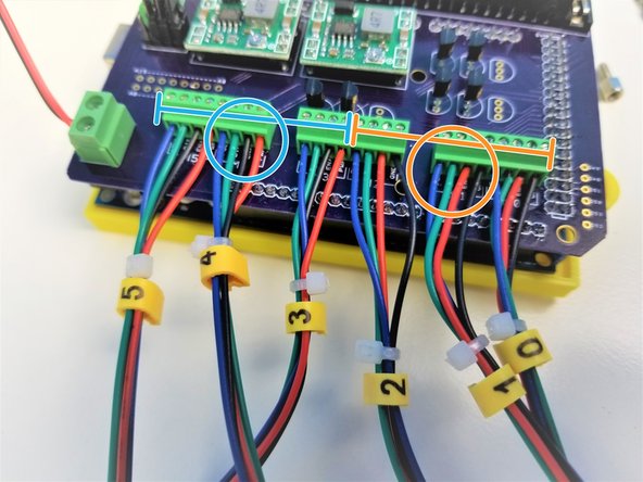
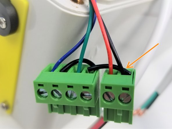
Start with M0 cables from the GX16 Aviation Plug and the screw terminal that's directly connected to PSU.
-
Start with Black, Green, Red, White
-
Repeat the same process for M1 and M2 as shown in the second picture.
-
-
-
Optional Step:
-
Use the Ferrule Crimp Pins to connect 22AWG power wires as shown in the first picture, do this for cable from PSU as well.
-
The same color code as bigger drivers applies to DM320T, just repeat step 30 with M3-5 Motor Wires
-
-
-
Congratulation! you've successfully finished assembling the Electronic Case! Go You!
-
![[3D] Electronic Case Package](https://d3t0tbmlie281e.cloudfront.net/igi/mcr/cbVbsoyjK53cHYlG.medium)


![2-Wire Power Cable 18AWG - [160mm]](https://d3t0tbmlie281e.cloudfront.net/igi/mcr/xtinC5UEy3oLGYLs.medium)
Cancel: I did not complete this guide.
One other person completed this guide.
