Introduction
This guide will show all the assembly steps for the Makelangelo 5, which can be purchased - fully assembled and tested - from http://marginallyclever.com/product/make...
Tools
Parts
No parts specified.
-
-
We want this to be easy for everyone. If anything is confusing or could be better, please use the comment button under every step to start a conversation about that step.
-
-
-
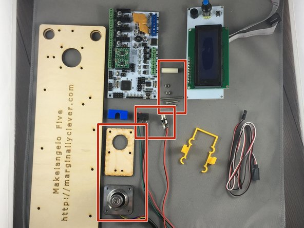
Gather all parts needed for assembly.
-
Gather required tools: socket wrech for M3 nuts, metric alan key for M3 socket head screws, phillips screwdriver, snips, and a soldering iron.
-
Do not start the assembly until you have all the parts and tools required. A half-finished robot is a liability and a heartache.
-
-
-
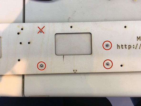
Insert M3x10 screws through the indicated holes and on the other side tighten M3 hex nuts.
-
-
-
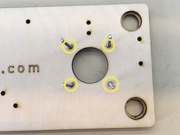
Insert four M3 x 35 screws through indicated holes
-
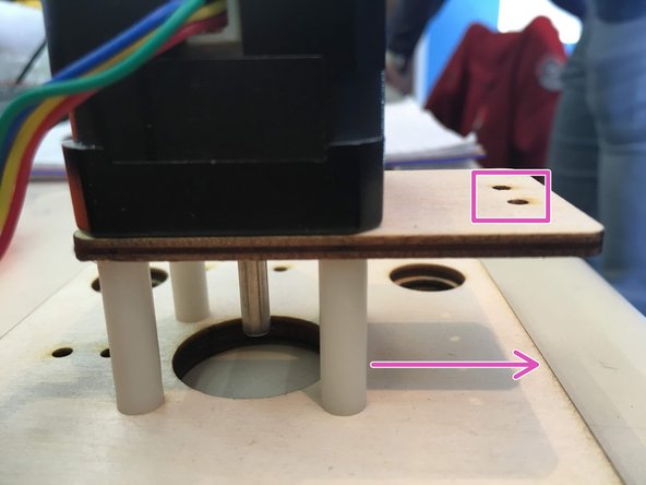
Slide four 25 mm spacers onto the screws and clip on motor bracket
-
Wood tab with the two holes facing bottom of the board
-
Place motor, lining up screws with the holes, screw in, and unclip the motor bracket.
-
Repeat for left-hand side
-
-
-
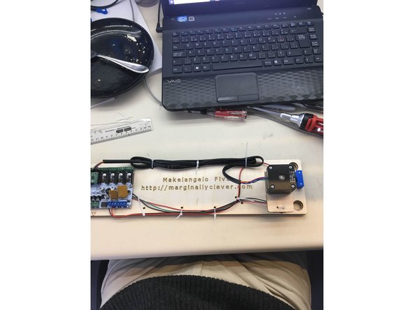
Find the 1m 3-wire dupont cables that have three colors, typically red/blue/black.
-
Cut the wire 43cm from one end. The second piece should be approximately 58cm. Strip the newly cut ends.
-
if you are doing multiple machines, cut them all into two piles, then strip them, then solder them. fewer task changes is faster production.
-
the short wire is for the left side of the machine. the long wire is for the right.
-
-
-
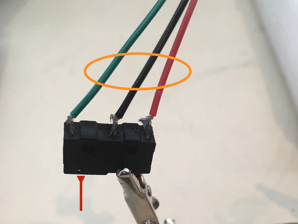
Solder three wires to each switch. From left to right the wire colors should be green, black, red. This assumes the actuator on the switch is also on the left.
-
You will need two switches for each Makelangelo.
-
It's a good idea to add a zip tie around all three wires, close to the switch. This will reduce wear and tear on any one solder connection.
-
-
-
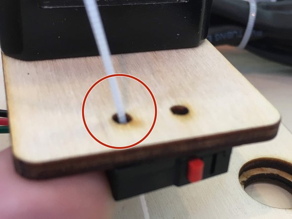
Through one of the two holes put a zip tie through one of the holes on the limit switch
-
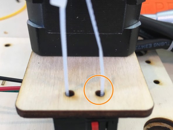
Bend the end of the zip tie around and place back up through the second hole
-
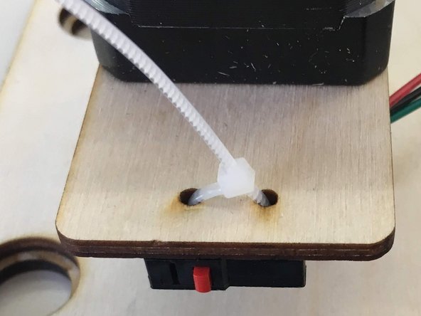
Zip the zip!!
-
-
-
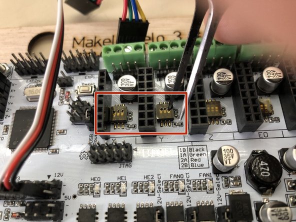
Make sure power is OFF during this step. Permanent damage to the electronics could result if power is on.
-
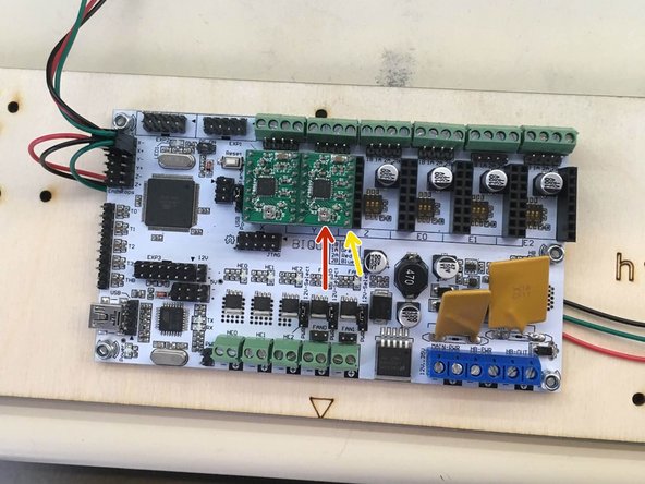
Using a tool with a fine tip, press the dip switches from north (default) to south. The dip switches set the microstepping. The firmware expects all switches to be down for 1/16th microstepping.
-
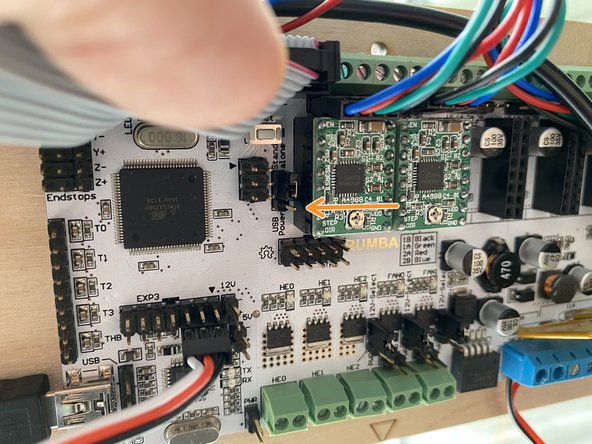
there are three pins marked USB/Stand-alone. By default new boards have a jumper connecting the south two pins, USB position. The jumper must be moved to the Stand-alone position connecting the north two pins. Note the empty south pin.
-
-
-
Adjusting drivers with power on - or even a large static charge from a metal tool - can kill them. Never turn the voltage dial with power on. Never plug/unplug motors with power on. Never plug/unplug drivers with power on. If possible use a plastic tool.
-
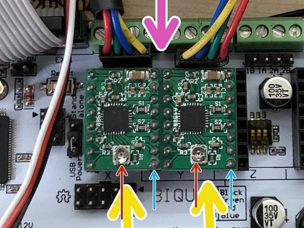
With power off, install the drivers on the X and Y axis of the RUMBA board. Note the voltage dial at the south side. Installing a driver upside-down will kill the driver.
-
Connect power to the robot, and get a multimeter. Turn the multimeter dial to 20v resistance.
-
Put the red lead of the multimeter on the dial in the bottom center of the driver.
-
Put the black lead on the bottom right pin of the driver. The target value is 0.17
-
Very small changes (5-10 degrees) are all that are needed to make big changes to the target value. a plastic flathead screwdriver works great.
-
Turn power off, adjust the dial, turn power on, measure the value, repeat until within +/-0.05 of target.
-
-
-
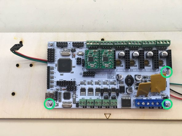
Put one hex nut on each of the M3x10 screws indicated. (The fourth is not required.)
-
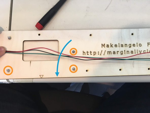
Place wires from right hand limit switch in between the screws for holding the board.
-
Put the RUMBA board on the screws and thread and tighten M3 hex nylock nuts onto the three screws circled. The fourth is not required.
-
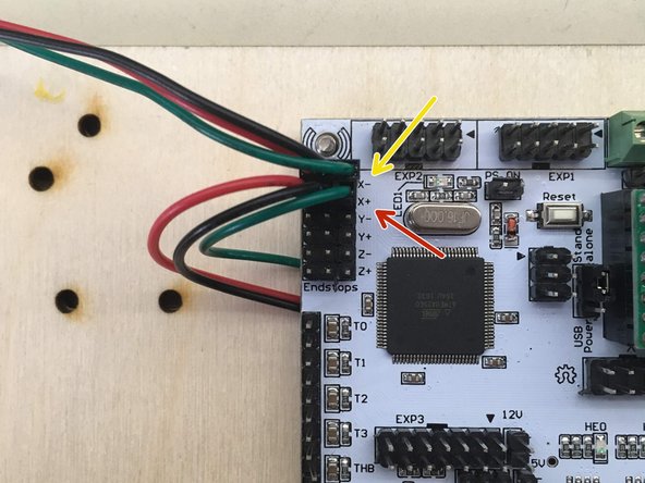
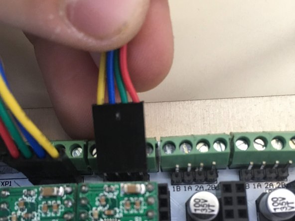
Plug the limit switches into indicated pins. the left switch connects to X- with the green wire on the right.
-
The right switch connects to X+ with the green wire on the right.
-
-
-
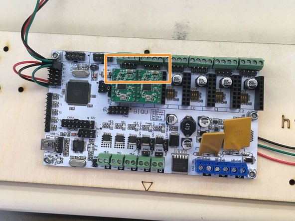
Locate proper pins
-
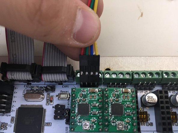
Plug the left motor into the left set of pins and the right motor into the right set
-
Make sure that the yellow wires on both are towards the center
-
-
-
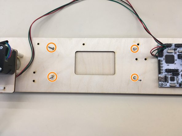
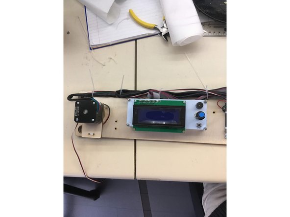
Insert four M3 x 35 screws into the indicated holes
-
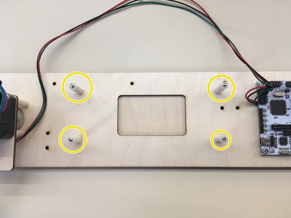
Slide on four 25 mm spacers onto screws
-
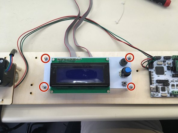
attach the LCD ribbon cables to the LCD panel with both pink lines to the left as shown in picture
-
Place the display onto the screws, with the knob towards the right side, and tighten four M3 hexnut nylocks onto the screws
-
-
-
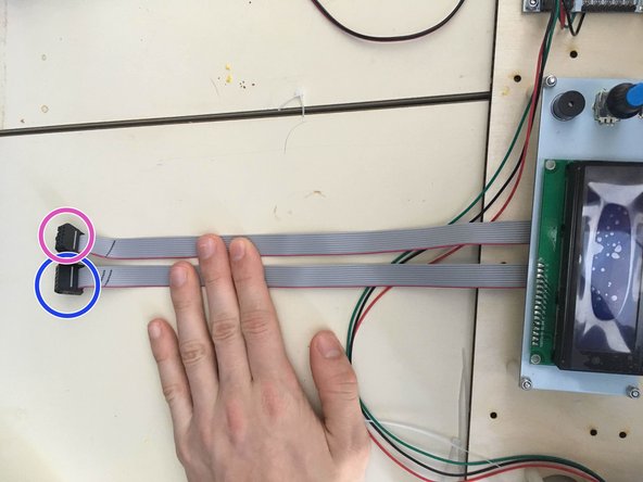
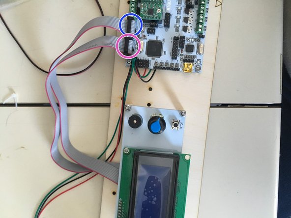
The left most cable coming from the LCD display goes into the right most set of pins, as displayed
-
The right most cable goes into the leftmost set of pins
-
When plugging the plugs onto the board, ensure that the wires are pointing towards the edge of the board
-
-
-
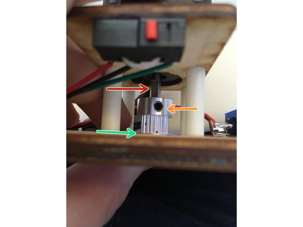
Slide a pully onto motor shafts. Locate the flat side of the motor shaft.
-
Use an alan key to tighten the set screw against the flat side of the motor shaft.
-
The edge of the pulley should be a little above the surface of the wood
-
Repeat for other side.
-
-
-
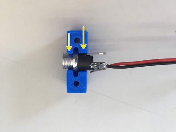
Take a pair of black and red wires 43 cm in length
-
Solder the black wire to the north pole and the red wire to the west of the power connector following the same techniques used for the switches.
-
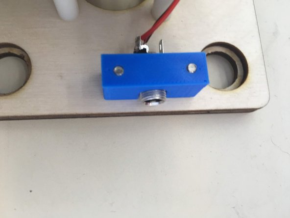
Slide the 12v power plug into holder. Note that once side of the holder is slightly larger than the other. It fits better the correct way around.
-
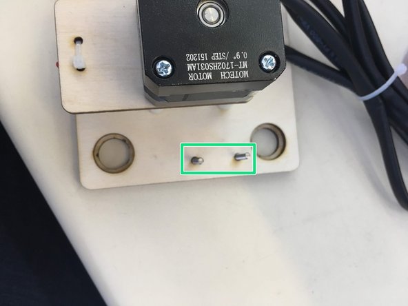
Thread two M3x10 screws into holder through the two extra holes beside the right-hand motor
-
Tighten until the plastic meets the wood and the screw is flush with the wood. Do not overtighten or the screw will strip the plastic and fall out.
-
-
-
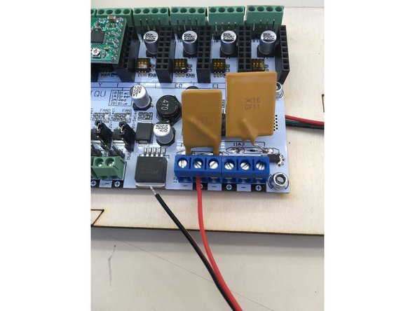
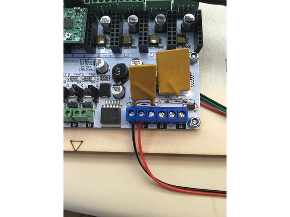
Insert wires from 12v power connector into terminal blocks ensuring that the red wire is inserted into the positive terminal and the black wire is inserted into the negative block
-
-
-
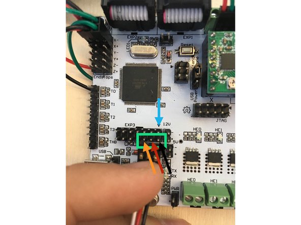
Plug the servo wire onto the board on the bottom row of the EXP3 block.
-
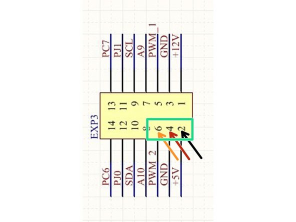
Note the black arrow head pointing to EXP3 pin 1.
-
The black wire lead of the connector goes into EXP3 pin 2.
-
The white wire lead of the connector goes into EXP3 pin 6.
-
That means the middle lead of the connector is in EXP3 pin 4.
-
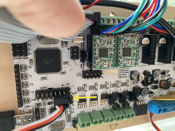
Notice here how there is one pin free on the right.
-
-
-
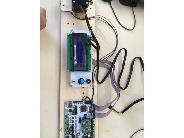
Contain all of wires to the board with zip ties using the extra holes spaced all around the board.
-
The goal is to lock down the wires as much as possible so that they cannot catch on anything and get pulled by accident.
-
When you are satisfied with the cable management, cut off the tail end of the zip ties.
-
-
-
plug a 12v2a power supply into the power connector on the right edge of the Makelangelo 5.
-
If the LCD panel does not turn on then probably the grey cables are reversed or plugged in backwards. There are only 4 possible ways to connect them.
-
Using the formula [Vref=8⋅Imax⋅Rcs] find the maximum voltage allowed to keep your stepper motors safe, for example if your motors have 68mΩ of resistance and can allow p to 0.33a then you can find your maximum voltage by rearranging the formula to be: Vref= 8⋅0.33a⋅6.8mΩ. Make sure your Makelangelo meets this by using a multimeter set at 2V.
-
Adjust the dial ONLY with power off. Changing the voltage while connected can destroy the stepper driver.
-
Do this adjustment for both motors. Save time by checking both before disconnecting power. A dial turn of only 10 degrees makes a big difference!
-
-
-
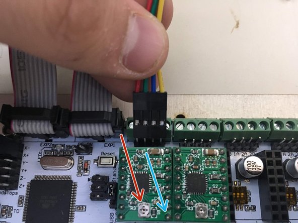
On each motor driver there is a voltage adjustment dial. NEVER turn the dial while power is connected or you will kill the driver.
-
In the bottom right corner is the GND pin.
-
A multimeter can measure the RMS current between these two pins. Ideally the RMS Current = Peak Current x 0.707. For a 0.3a stepper motor the RMS current would be 0.21
-
Measure the RMS current; turn off power; turn the dial 5-10 degrees. Repeat until the RMS current is correct.
-
Test your machine again to ensure smooth moving motors that do not get very hot. (they will still be warm to the touch.)
-
-
-
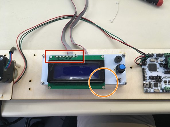
the green part of the screen is attached to the white part only here. When the motors turn vibration is picked up by these two parts and they buzz against each other.
-
A small piece of foam or folded tissue paper inserted between the green and white parts here will dampen the vibration and stop the noise.
-
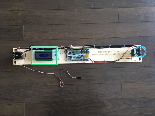
Congratulations! The core of the makelangelo 5 is now completely assembled.
You will still need to assemble the pen holder and upload firmware before you can run the robot. Both of these steps are found in other guides.
For more help and robots, join us on Discord at https://discord.gg/QtvHqAv8yp
Congratulations! The core of the makelangelo 5 is now completely assembled.
You will still need to assemble the pen holder and upload firmware before you can run the robot. Both of these steps are found in other guides.
For more help and robots, join us on Discord at https://discord.gg/QtvHqAv8yp
Cancel: I did not complete this guide.
2 other people completed this guide.


