
-
-
Package #2
-
Alan Keys
-
Socket Head Driver
-
Plier [Opt.]
-
-
-
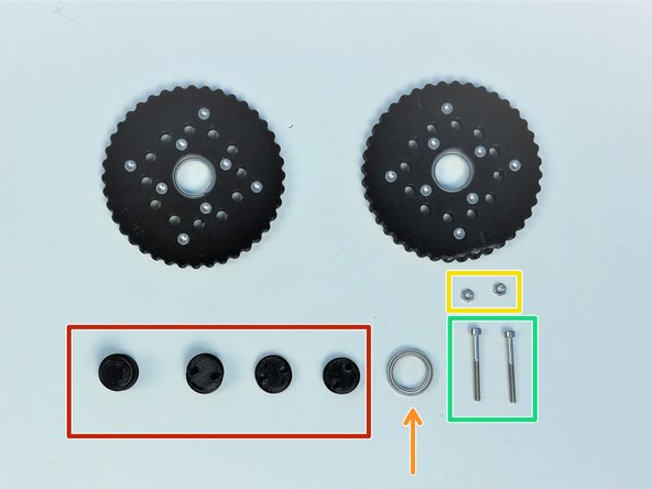
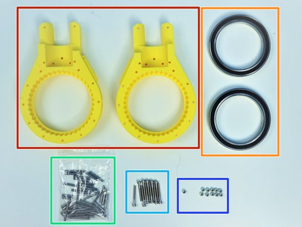
Prepare the following components:
-
[3D] - 2GB Shoulder GB Rotors
-
6702 Bearings [15x21x4mm] (x2)
-
M3x5mm Screws (x16)
-
M3 Hex Nuts (x16)
-
NOTE:
-
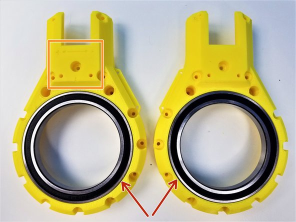
Shoulder Gearbox Rotor consist of 4 similar looking parts, Be aware of T Label and B Label
-
Also Be aware of the Nut Insert vs. Screw Head Insert
-
-
-
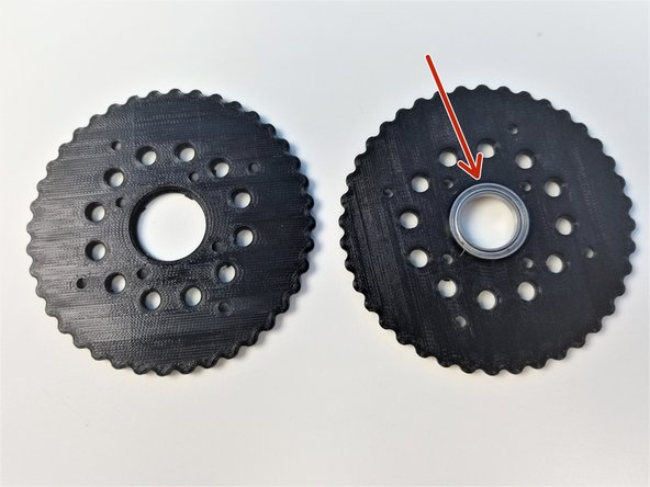
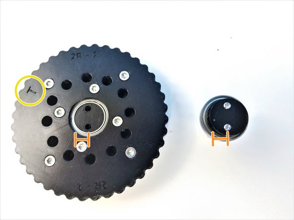
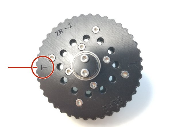
The process for "T" Rotor and "B" Rotor is the same. We will use T rotor as our guide and repeat the same process for B rotor
-
Insert 6702 Bearing on one half of the T Rotor
-
Place the other half and clamp the Bearing together
-
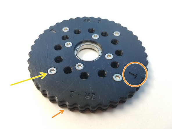
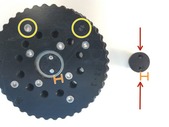
Make sure to align the T label, The holes and the teeth won't line up if this isn't done correctly.
-
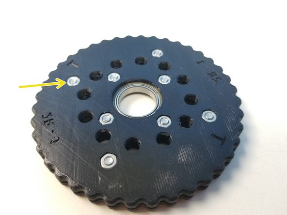
Insert M3x5mm Screws and Hex Nuts on each half of the Rotor and tighten all the Screws.
-
Repeat the same Process for B Rotor
-
-
-
Prepare the following components:
-
Assembled Rotors
-
[3D] - 2GB Eccentric Shafts
-
6702 Bearing [15x21x4mm] (x1)
-
M3 Hex Nuts (x2)
-
M3x30mm Screws (x2)
-
-
-
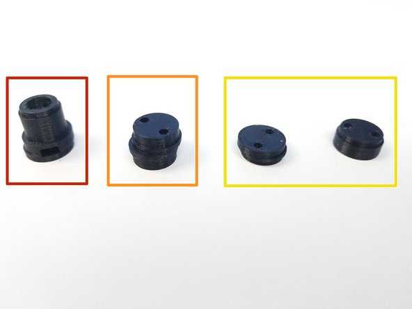
Input Shaft Consist of 4 components:
-
Motor Shaft Coupler
-
Eccentric Cam
-
Shaft Holder Cams (thin piece & thicker concentric piece)
-
Shaft Holder Cams prevent the input shaft to go off on the axis of rotation
-
-
-
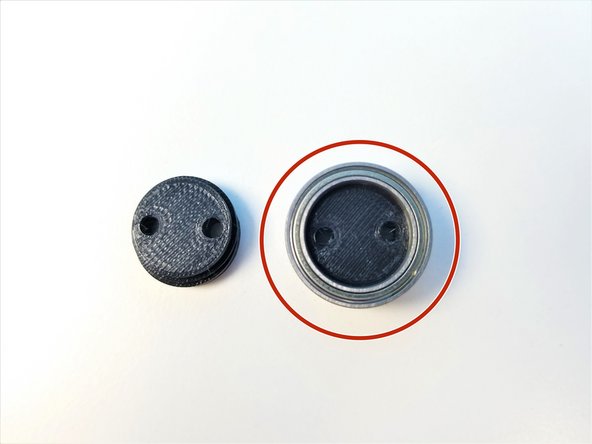
Put the 6702 Bearing on the Thicker Concentric piece of the Shaft Holder
-
Notice that the thinner piece of the Shaft Holder has 2 sides, one where screw lined up to the center of the face and other which is eccentric
-
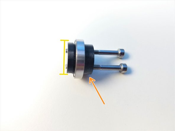
Clamp Shaft Holder Cam pieces using M3x30mm Screws
-
Thicker piece is the Screw Head side,
-
Only screw in until the tip of the screw is flushed with the face of the thinner piece
-
-
-
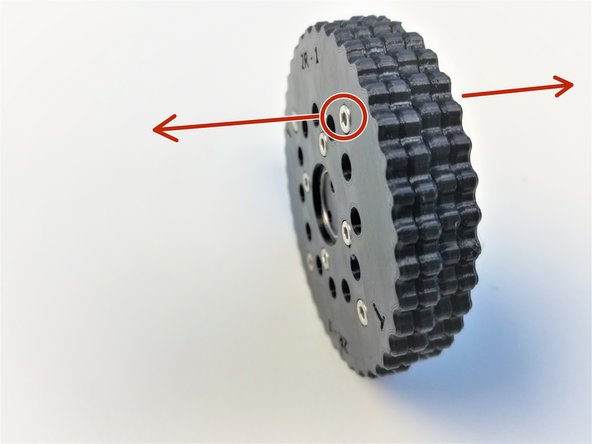
Insert Top & Bottom Rotors on the Eccentric Cam
-
The Screw Head side of each rotor is facing away from each other
-
Align the Eccentric Cam and Shaft Holder Cams and partially screw in the M3x30mm Screws.
-
Check that the T Rotor is facing the Shaft Holder Cam
-
-
-
Insert M3 Hex nuts on the side of the Motor Shaft Coupler
-
Align the Coupler offset and Eccentric Cam offset
-
Make sure the B Rotor and its Screw Head side facing the Coupler
-
Screw in the rest and Tighten it
-
-
-
Prepare the following components:
-
Assembled Input Shaft and Rotors
-
[3D] - 2GB Shoulder GB Housing Top Halves
-
6813 Bearings [65x85x10mm] (x2)
-
Steel dowel pin 91595A130 - [3x24mm] (x41)
-
M3x25mm Screws (x11)
-
M3 Nylock Nuts (x11)
-
-
-
Insert 6813 Bearings on the Housing parts
-
3D-printed housing parts consist of a motor side part and a sensor side part
-
The side with Directional Label is the Motor Side
-
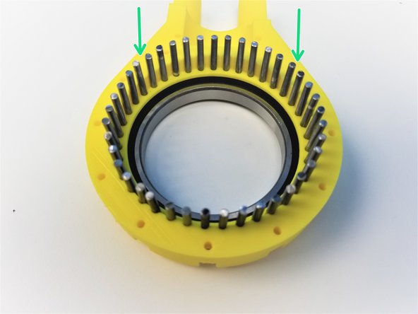
Insert all 41 Steel Pins on the Sensor Side Half of the Housing.
-
-
-
Alignment of the rotor is critical for these gearbox to work.
-
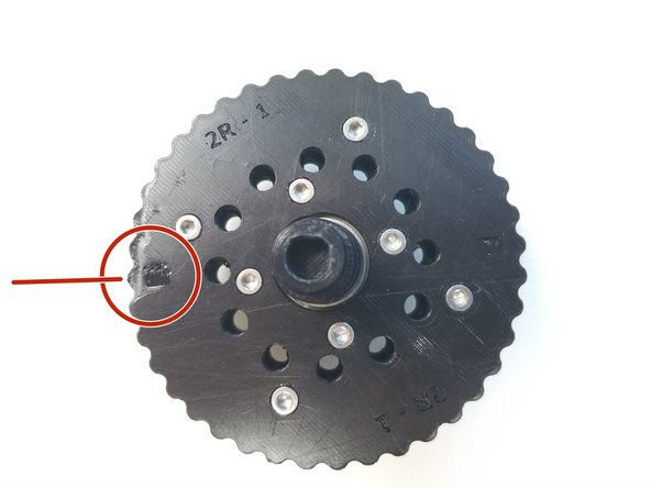
Notice that there are 2 "T" Labels on the T rotor, and same with B rotor with "B" Labels
-
T is aligned in between 2 teeth of the Top Rotor while B is aligned to the middle of a tooth
-
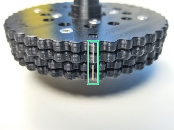
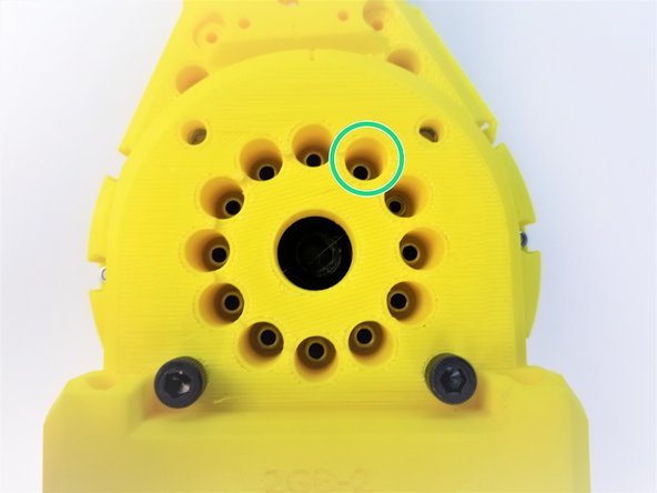
Make a Sharpie Mark in between the teeth of T Rotor Where the "T" is Labeled
-
For B Rotor, Make a sharpie mark on the tooth where the "B" is Labeled.
-
The Correct Alignment will look something like the Third Picture
-
-
-
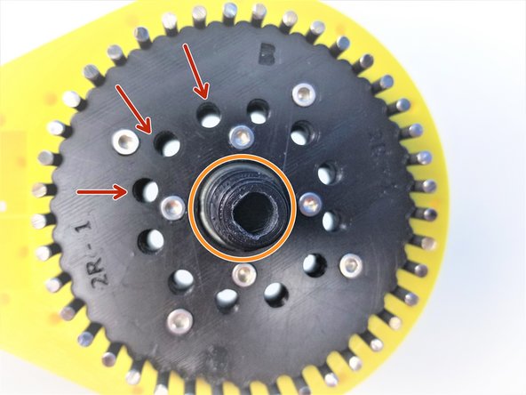
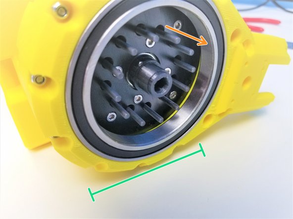
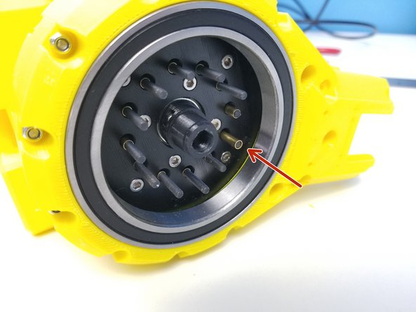
Once the Rotor is Properly aligned, all 12 inner holes will have the same space between them when looking directly above it
-
The Angle of the picture taken of the aligned Rotors are a bit off.
-
Carefully insert the Rotor while maintaining this position on the Housing with the pins.
-
Make sure the Motor Shaft Adapter side of the shaft is Pointing out
-
Press the second half of the housing into place.
-
Verify that you can manually turn the eccentric shaft in the center and that the rotors smoothly turn inside the housing. Tight printing and misaligned rotors can cause the gearbox to jam.
-
Clamp the other half of the Housing using M3x25mm Screws and Nylock Nuts
-
Secure tightly using the 5.5mm Socket Driver to hold the Nuts.
-
-
-
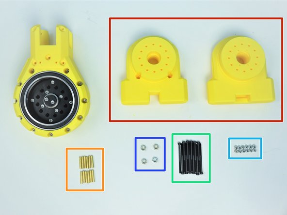
Prepare the following components:
-
Assembled Shoulder Gearbox Top
-
[3D] - 2GB Shoulder GB Bottom Halves
-
Brass Tubes [3.5x18.5mm] (x12)
-
M3x45mm Screws (x12)
-
M3 Nylock Nuts (x12)
-
M5 Hex Nuts (x4)
-
-
-
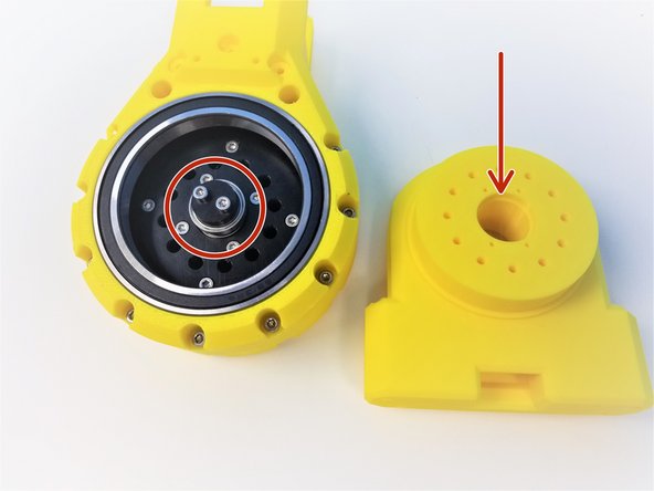
Align the Bearing Insert of the Gearbox Bottom Sensor Side Piece to the Shaft Holder Cam Bearing of the Input Shaft
-
Insert M3x45mm Screws all the way through
-
If Screws aren't going in correctly, you will have to re do the steps, go to aligning the Rotor Step
-
Keep the Gearbox laying on its side for easier assembly
-
-
-
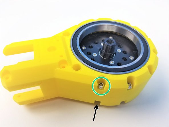
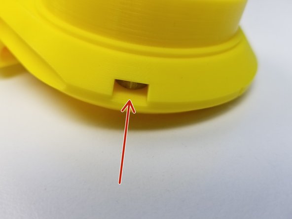
Insert M5 Hex Nuts on the side insert of the Motor Side Bottom Half
-
Insert the other two M5 Hex Nuts on the bottom inserts
-
[Opt.] if the nuts are too loose in the insert, use M5x20mm Screws (or any M5 screws) to hold it in place during assembly
-
-
-
While keeping the Gearbox on its side, insert 3.5x18.5mm Brass Tubes on each Screws
-
Insert the Motor Side of Shoulder Gearbox Bottom and secure it with M3 Nylock Nuts using the Alan Key and Socket Driver
-
-
-
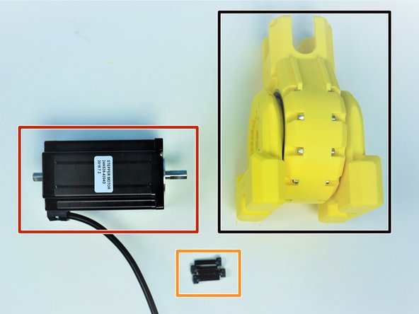
Prepare the following components:
-
Assembled Shoulder Gearbox
-
NEMA24 100mm Motor
-
M5x20mm Screws (x4)
-
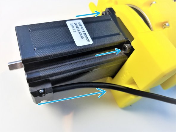
Align the D-Cut of the Motor Shaft to the Gearbox Input Shaft and insert the motor all the way through.
-
Align the motor body so the cable is pointing towards the bottom and secure the position using M5x20mm Screws
-
-
-
Prepare the following components:
-
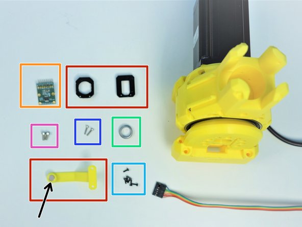
[3D] - Sensor Adapter and Magnet Holder Parts
-
AS5147 Sensor [right angle headers on Label Side]
-
8x2.5mm Neodymium Magnet
-
6701 Bearing [12x18x4mm] (x1)
-
M2x6mm Screws (x6)
-
M2x10mm Screws (x2)
-
M3x8mm Screws (x2)
-
-
-
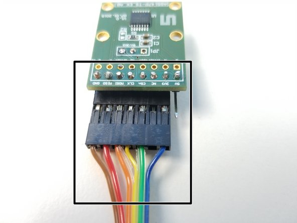
Also prepare 6-pin Ribbon Cable F/O - Brown to Blue {sensor 1 Shoulder} - [365mm]
-
There is a separate assembly guide for all sensor cable which shows the length of each as well.
-
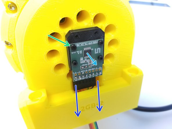
Connect the Cable to the AS5147 Sensor as shown in the second picture
-
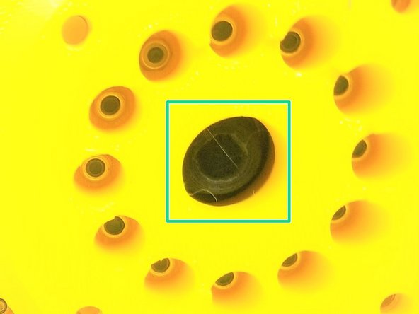
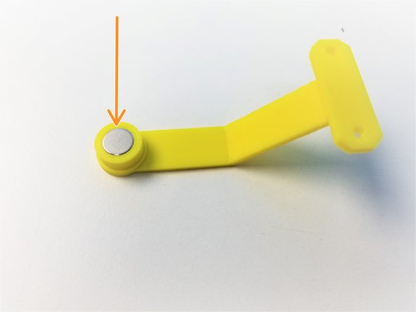
Insert the Neodymium Magnet in the Shoulder Magnet Holder
-
-
-
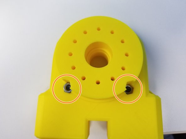
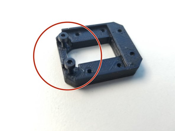
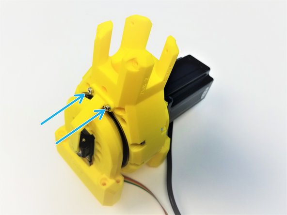
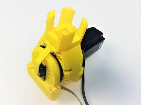
Partially screw in two M2x6mm screws in the Sensor Adapter with the screw head insert.
-
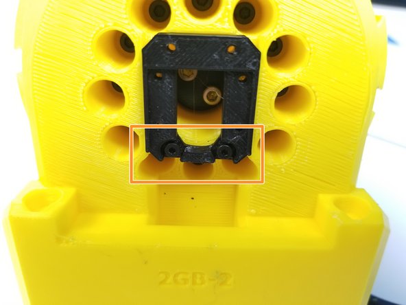
Secure the Sensor Adapter to the Sensor Side of the Gearbox with 2 screw on the bottom side of the 4 holes
-
Feed the Sensor Cable through the Tunnel
-
Then use the remaining M2x6mm Screws to Secure the Sensor to the Sensor Adapter
-
Chip is facing outward
-
-
-
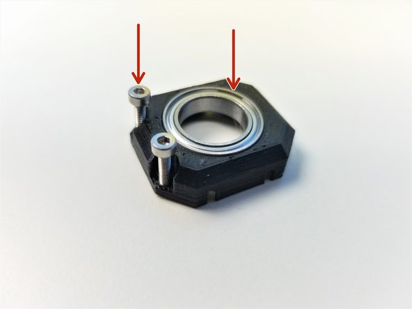
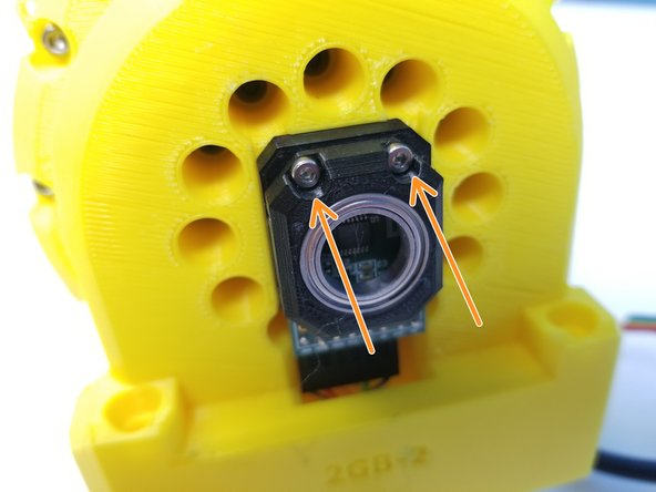
Insert 6702 bearing in the Sensor Bearing Holder part and partially screw in M2x10mm screws
-
Secure the Sensor Bearing Holder to the Sensor Adapter
-
Use M3x8mm Screws to secure the Magnet holder to the Shoulder Gearbox Top
-


![[3D] - 2GB Shoulder GB Rotors](https://d3t0tbmlie281e.cloudfront.net/igi/mcr/AgEctOPHD6Fl5Y1C.medium)
![[Opt.] if the nuts are too loose in the insert, use M5x20mm Screws (or any M5 screws) to hold it in place during assembly](https://d3t0tbmlie281e.cloudfront.net/igi/mcr/UujeZAdTeITaFNvg.medium)
![Also prepare 6-pin Ribbon Cable F/O - Brown to Blue {sensor 1 Shoulder} - [365mm]](https://d3t0tbmlie281e.cloudfront.net/igi/mcr/PBxpKS6twaEqZbml.medium)
Cancel: I did not complete this guide.
One other person completed this guide.
