
-
-
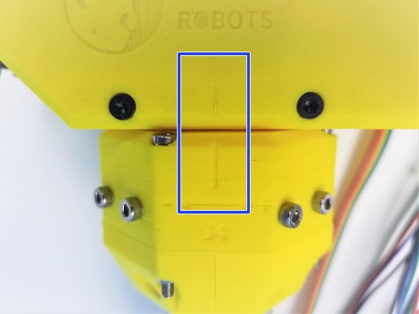
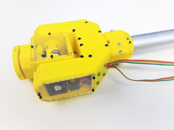
Assembled Picasso Box
-
Assembly Ulna Gearbox & Elbow Tail
-
[3D] - 6E Picasso Wrist Gearbox Components
-
[3D] - 5A Fork Components
-
Alan Keys
-
Socket Head Driver
-
Plier [Opt.]
-
-
-
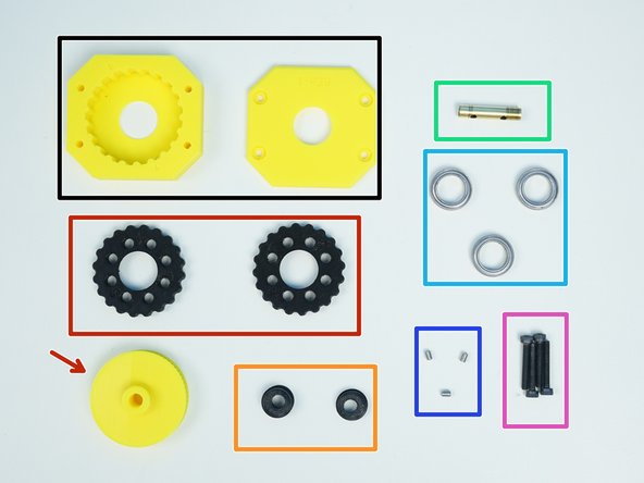
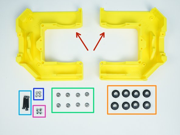
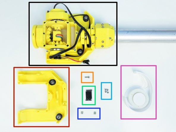
Prepare the following components:
-
Assembled Picasso Box
-
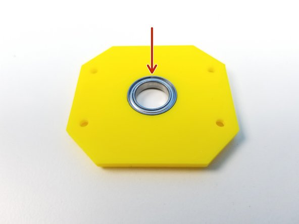
[3D] - 6Ea Picasso GB Output Disks
-
6706 Bearing [30x37x4mm] (x1)
-
M3x10mm Screws (x4)
-
M3x20mm Screws (x8)
-
M3 Hex Nuts (x8)
-
-
-
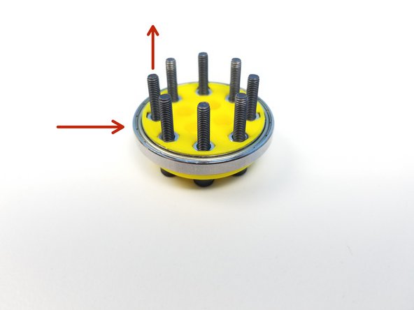
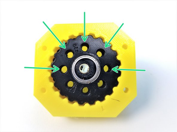
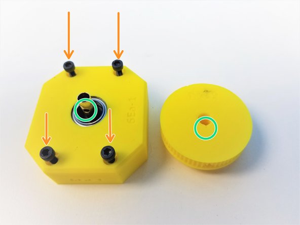
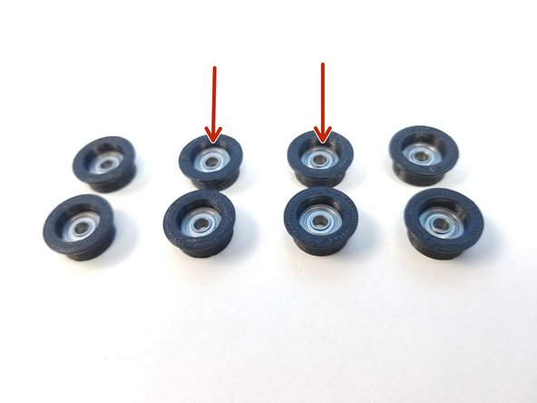
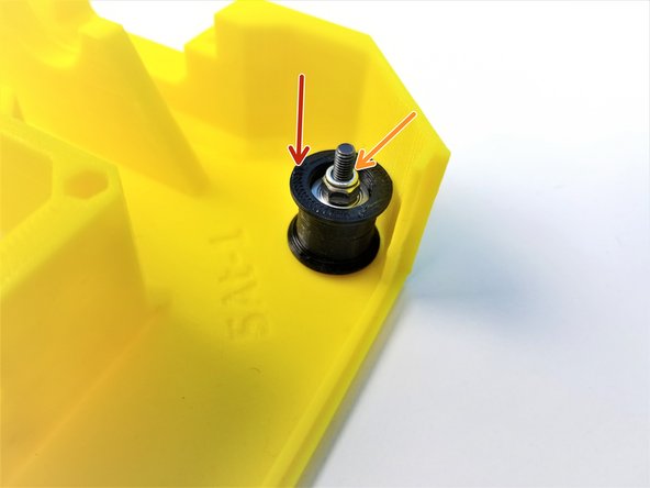
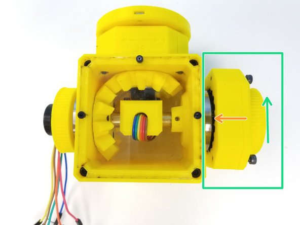
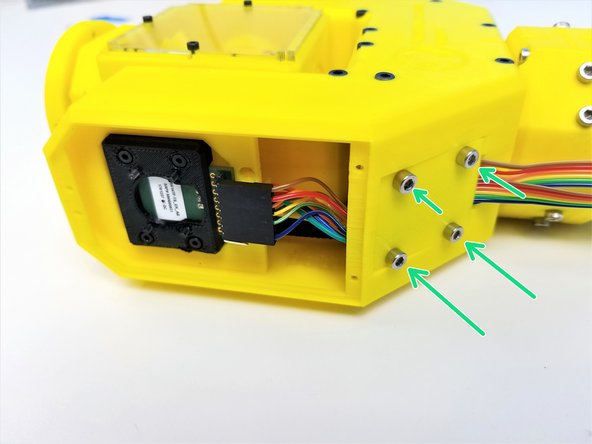
Clamp 6706 Bearings with two Output Disk components using M3x20mm screws and Hex Nuts
-
Tighten these nuts as well
-
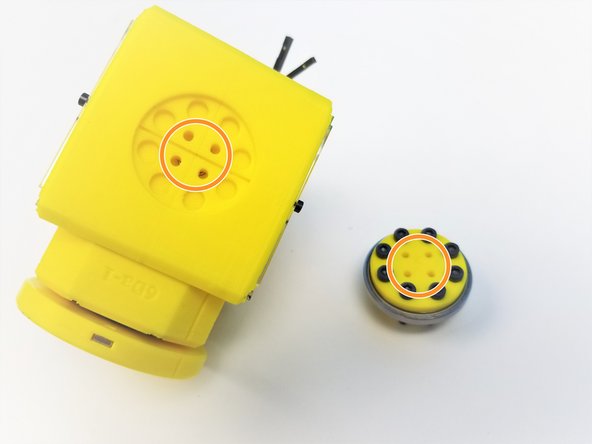
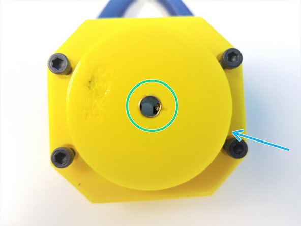
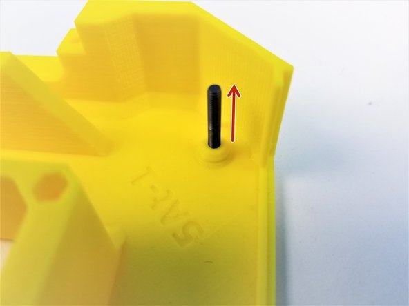
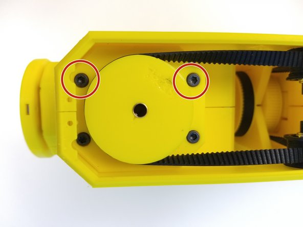
Align the 4 Middle Holes of Clamped Output Disk to the side of the Picasso Box
-
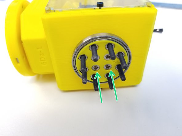
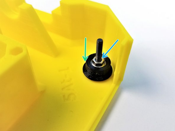
Secure the clamped output disk to the side of the Assembled Picasso Box using M3x10mm Screws
-
-
-
Prepare the following components:
-
[3D] - 6Ea Picasso GB Housing
-
[3D] - 6Ea Picasso GB Rotors & 6PE Pulley Gear
-
[3D] - 6Ea Picasso GB Eccentric Cams
-
Brass Tube [7/32' x 25.95mm]
-
6701 Bearings [12x18x4mm] (x3)
-
M3x4mm Set Screws (x3)
-
M3x20mm Screws (x4)
-
-
-
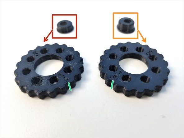
Eccentric Cams
-
"Thin/Top" Eccentric Cam
-
"Thick/Bottom" Eccentric Cam
-
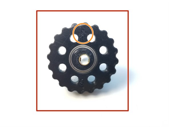
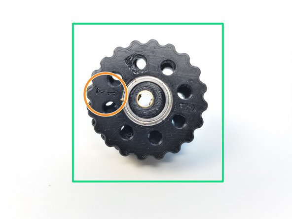
Rotors
-
Make a sharpie mark on the side of the Rotor where it lines up with the B and T label on each Rotors
-
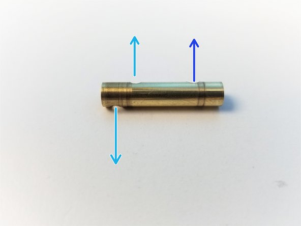
Brass Tube
-
Tube end with the two drilled holes = Cam End
-
Tube end with the one drilled hole = Pulley End
-
-
-
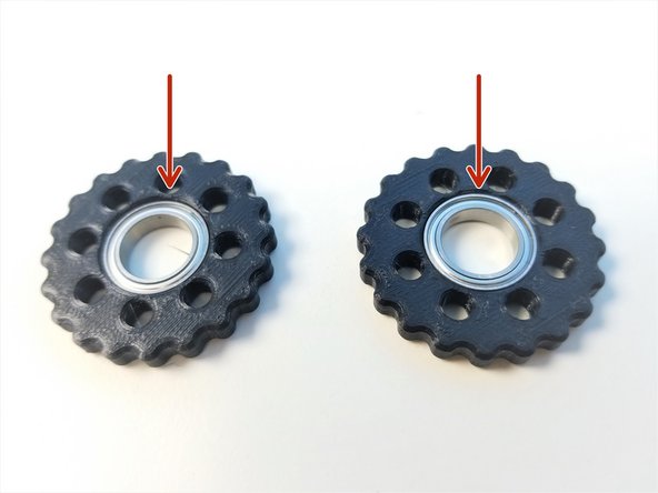
Insert 6701 Bearings to both Top and Bottom Rotors as well as the Top Housing
-
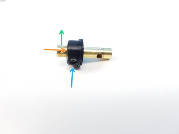
Slide the Bottom Eccentric Cam to the 2nd hole from the edge in the Cam End of the Brass Tube
-
First hole is on the other side of the Tube
-
Align the set screw holes and screw its place using the M3x4mm Set Screw
-
-
-
Slide the Bottom Rotor to the Bottom Eccentric Cam
-
Label Side of the Rotor is facing the Cam End
-
Repeat the process with the Top Eccentric Cam and Rotor
-
Label Side of the Rotor is facing the Cam End
-
-
-
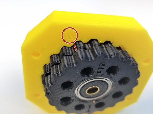
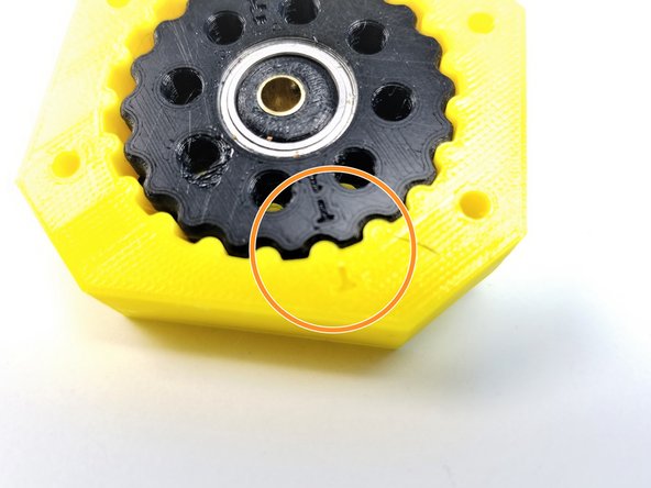
Align the Side Sharpie mark on the Bottom Rotor to the "B" label on the Housing and slide only the Bottom Rotor into the Housing
-
Align the Side Sharpie mark on the Top Rotor to the "T" labelled on the Housing and slide the rest of the Rotor in.
-
If everything went smoothly, the gap between 8 holes on each rotor should be equally spaced
-
Verify that you can manually turn the eccentric shaft in the center and that the rotors smoothly turn inside the housing. Tight printing and misaligned rotors can cause the gearbox to jam.
-
-
-
Insert 6701 Bearing on the Top Housing
-
Secure the Top Housing to the Rotor Housing using the M3x20mm Screws
-
DON't screw all the way in. Just to the flushed to the bottom of the Main Housing
-
Align the Pulley Gear to the Set Screw and slide in the Pulley gear to the Brass Tube
-
Secure it using M3x4mm Set Screw
-
-
-
Prepare the following components:
-
[3D] - 5Aa Fork {Bottom & Top}
-
[3D] - 5I Idler Bearing Cover (x8)
-
MF83 Flanged Bearings [3x8x4mm] (x8)
-
M3x20mm Screws (x4)
-
M3 Hex Nuts (x4)
-
M3 Nylock Nuts (x4)
-
-
-
Insert MF83 Bearings into the Bearing Sleeves
-
Insert the M3x20mm Screw in to the Fork Half where there's a chamfered peg on the inner face
-
Slide one of the Bearing Sleeves to the M3x20mm Screwss with the flanged part on the bottom
-
Use M3 Hex Nut to secure the Bearing Sleeve in place
-
-
-
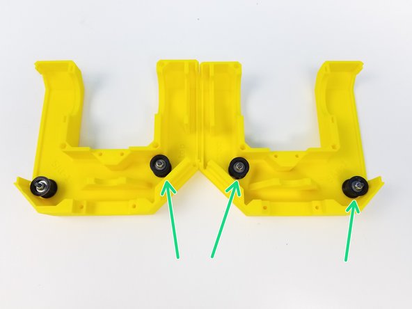
Insert another one of the Bearing Sleeves on the M3x20mm Screws but this time with the flanged part facing up
-
Use M3 Nylock Nuts to secure it in place
-
Repeat the procedure for 3 other locations.
-
-
-
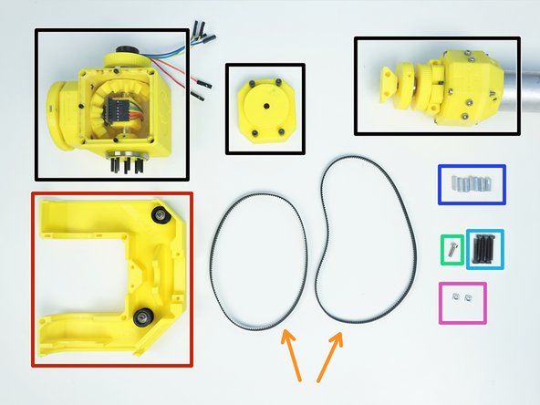
Prepare the following components:
-
Assembled Ulna Gearbox, Picasso Box and Wrist Gearbox
-
Fork Bottom {w/ Idler installed}
-
Timing Belt GT2-336mm & GT2-400mm
-
M3x10mm Screw (x1)
-
M3x22mm Screws (x6)
-
M3x4.5x12mm Hex Standoffs (x7)
-
M3 Square Nuts (x2)
-
-
-
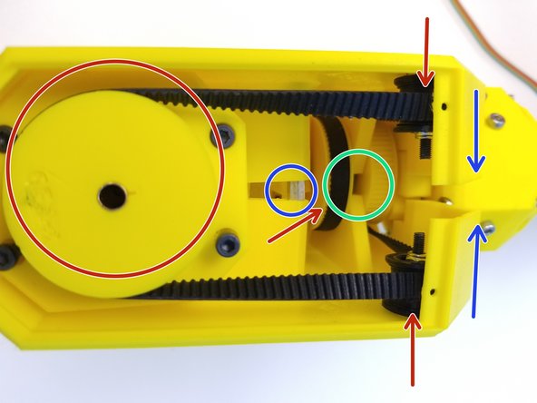
Place the GT2x400mm Timing Belt on the outer pulley on Assembled Ulna Gearbox
-
Place the GT2x336mm Timing Belt on the inner pulley
-
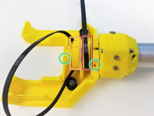
Align the Ulna Sensor Plate and Ulna Output Gearbox to the Fork Bottom with the Hex Standoff insert pointing upward
-
Insert M3x4.5x12mm Hex standoffs and secure its place using M3x22mm Screws
-
Use M3x10mm Screw in this location
-
-
-
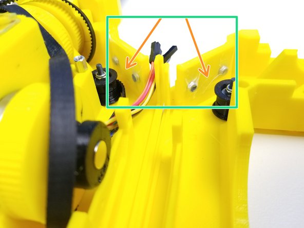
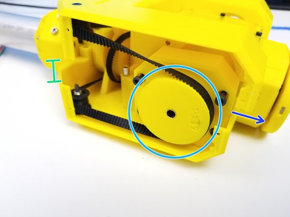
Insert the Picasso Output pins to the Picasso Gearbox
-
Rotate the Input Pulley of the Picasso Gearbox to align the gearbox housing
-
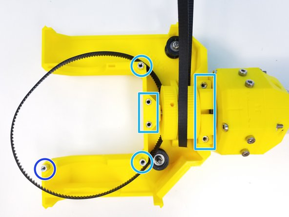
Insert the assembled Picasso Box into the Bearing Slots of the Fork Bottom
-
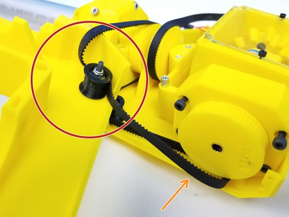
Make sure to wrap the Timing Belts on both Pulley Gears AND the Bottom Idlers
-
The SMOOTH SIDE of the Belt on the IDLERS
-
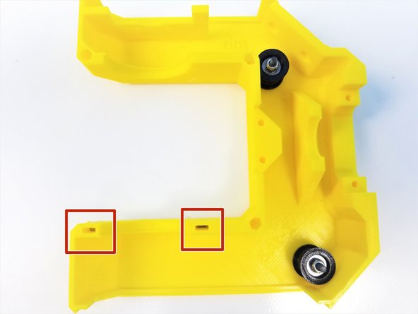
Insert M3 Square Nuts in the Square Nut insert on the Fork Bottom
-
Secure the Picasso Gearbox by tightening the bottom screws on the Gearbox Housing
-
-
-
Prepare the following components:
-
Fork Bottom Prepared
-
Fork Top {w/ Idlers Installed}
-
M3x10mm Screw (x1)
-
M3x25mm Screws (x6)
-
M3 Nylock Nuts (x4)
-
M3 Square Nuts (x2)
-
[Opt.] - Tape
-
-
-
Insert the M3 Square Nuts in the Fork Top
-
Insert the M3 Nylock Nuts in both Fork Top and Bottom on the side wall
-
Optionally, put tape over the nuts as the friction fit alone may not be enough to keep them on.
-
-
-
This step may be the hardest to execute so follow through carefully. Use Alan Key as a "hook" if you need to
-
Align the 400mm GT2-Timing Belt {outer belt} to the Top Idler
-
Take the Belt off of the Gearbox Pulley if you need to.
-
Make sure the SMOOTH side of the belt is on the Idler
-
Rotate the Top Fork and let it FLOAT over the Bottom Fork
-
Put the 400mm Belt back on the Pulley
-
Notice that the Top Fork is shifted forward relative to the Bottom Fork
-
While the Fork is shifted forward, put the 336mm GT2-Timing Belt on the Inner Pulley on the other side
-
-
-
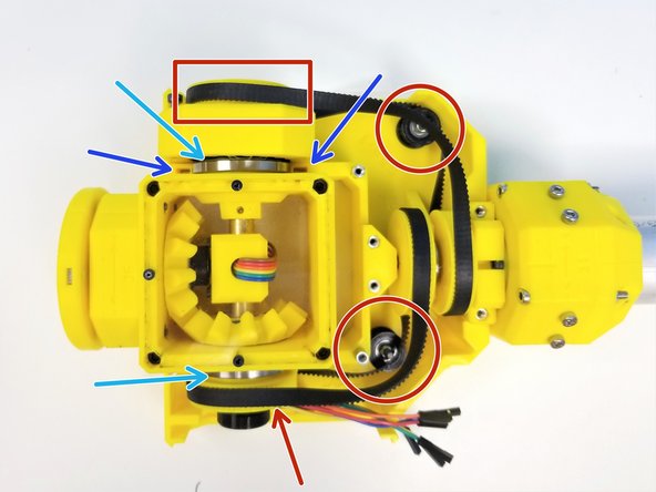
Make sure the both Inner and Outer Belts are on ALL the Pulley Gears
-
Shift the Top Fork back and align the "Pulley Separating Wall"
-
Double check that the Picasso Gearbox Side is all good too
-
Once all Hex Standoffs are aligned too, Clamp the Top Fork down
-
-
-
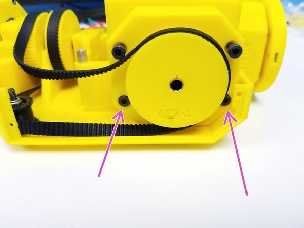
Secure the Picasso Gearbox to the Top Fork by tightening the top screws on the Housing
-
Use M3x25mm Screws and M3x10mm screw to secure the Top Fork to the Bottom Fork
-
-
-
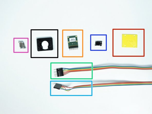
Prepare the following components:
-
[3D] - AS6147 Sensor Adapter 2
-
[3D] - 5Ac Fork Cable Clamp
-
AS5147 Sensor {right angle header on the label side}
-
6-pin Ribbon Cable M/O - Brown to Blue {sensor 5 Hand} - [1470mm]
-
6-pin Ribbon Cable F/O - Brown to Blue {sensor 4 Wrist} - [1520mm]
-
M2x6mm Screws (x8)
-
M3x10mm Screws (x4)
-
-
-
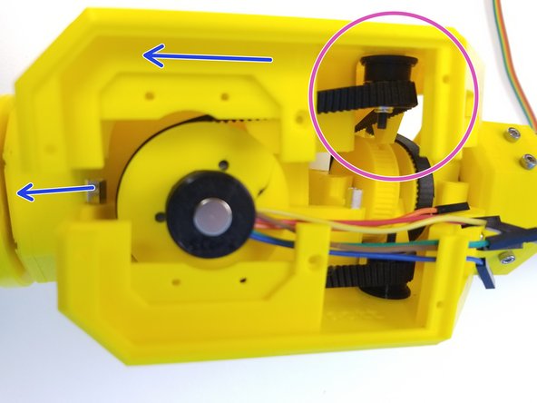
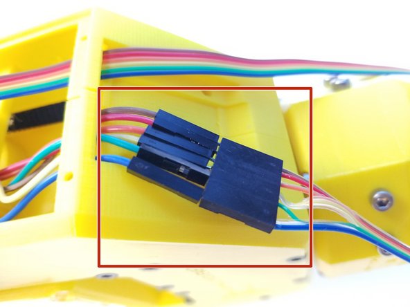
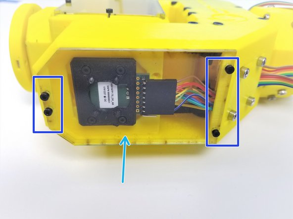
Connect the Hand Sensor Cable Extension to the Wires that comes out of the Picasso Box {Hand Sensor}
-
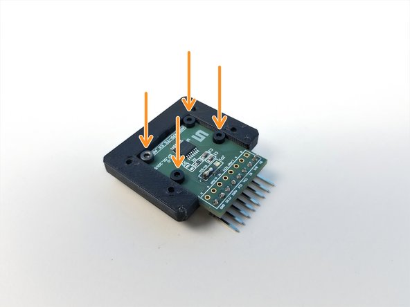
Mount AS5147 Sensor to the Sensor Adapter 2 using M2x6mm Screws
-
Insert the Wrist Sensor Cable {Female} through the Cable Clamp
-
Connect the Wrist Sensor Cable to AS5147 Sensor
-
If you don't remember the Connection Orientation from previous steps, just copy the picture.
-
-
-
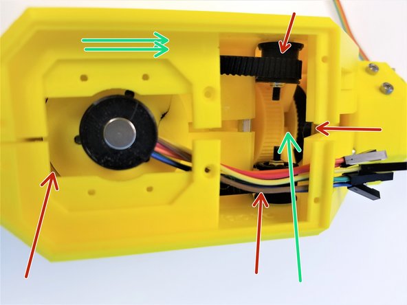
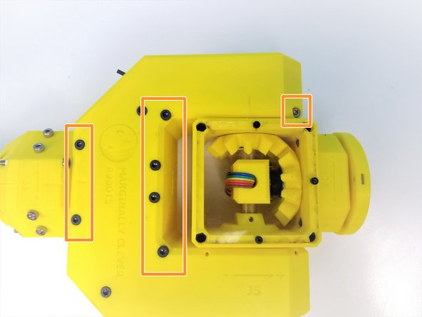
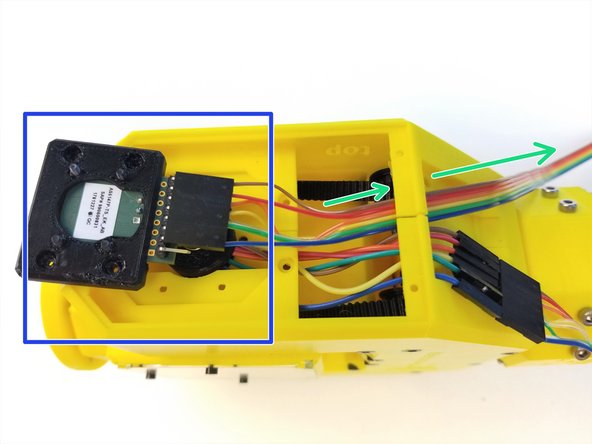
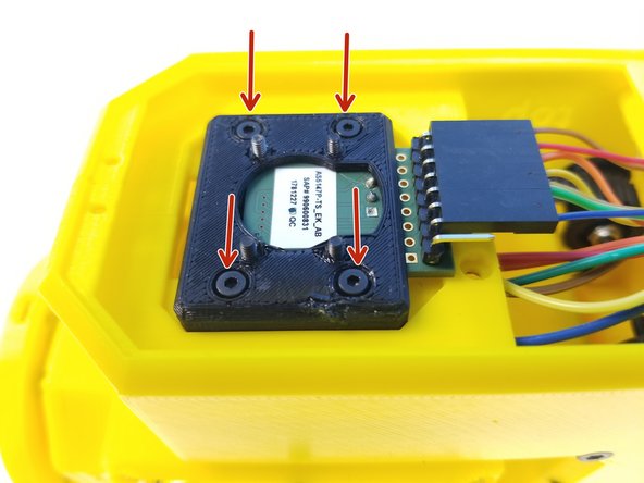
Use M2x6mm Screws to secure the Sensor Adapter to the Fork
-
Organize the Cables on the Cable Clamp area
-
The Hand Sensor Connector is below the Wrist Sensor Cable
-
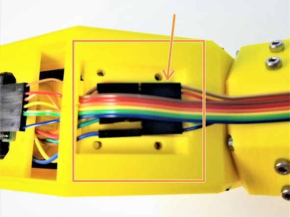
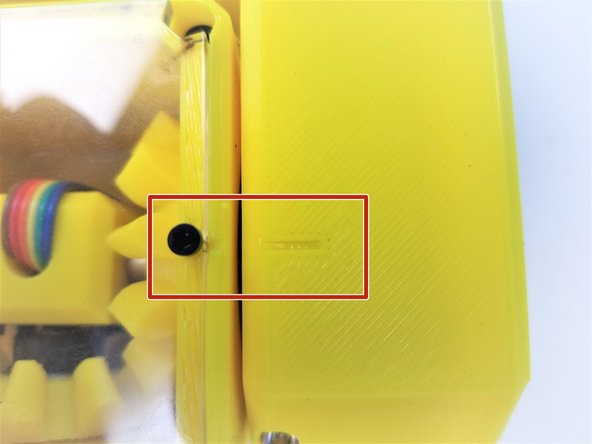
Use M3x10mm Screws to clamp the sensor cables with Fork Cable Clamp Plate
-
There's only one orientation that the Clamp Plate can go on,
-
Make sure the Version Label is facing the Cable
-
Chamfered Part is where the Cable comes Out
-
-
-
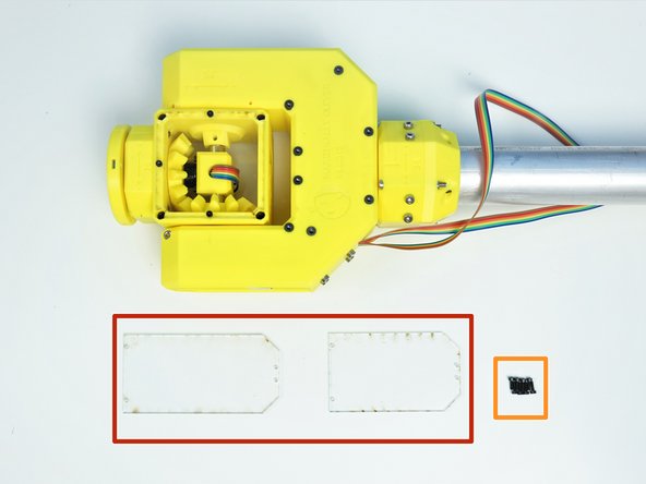
Prepare the following components:
-
[LSR] - Fork Acrylic Plates {Large & Small}
-
M2x6mm Screws (x8)
-
Small Acrylic Plate goes on the Sensor Side
-
Large one goes on the Wrist Gearbox Side
-
Secure them with M2x6mm Screws
-
-
-
Rotate the Motor Shafts on the Elbow Tail Side to rotate the joints
-
Align the Picasso Box to the Fork
-
Align the Fork to the Ulna Gearbox
-
Align the Hand to the Picasso Box.
-
Movement for all three joints should be smooth and without play in both directions.
-


![[LSR] - Fork Acrylic Plates {Large & Small}](https://d3t0tbmlie281e.cloudfront.net/igi/mcr/3BYQU4p6n3x2opJu.medium)
Cancel: I did not complete this guide.
One other person completed this guide.
