Introduction
This guide will show all the assembly steps for the Makelangelo 5, which can be purchased - fully assembled and tested - from https://www.marginallyclever.com/product...
Parts
No parts specified.
-
-
2x NEMA17 stepper motors
-
8x 25mm spacers
-
8x M3x35 screws
-
2x zip ties
-
2x micro switches
-
2x 1m blue/black/red cables
-
the laser cut wood parts
-
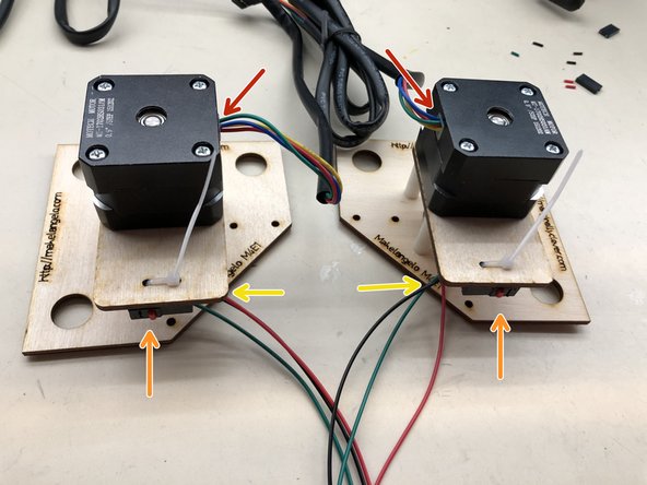
The two halves are mirror images of each other. Pay close attention so that you do not have to redo any work.
-
-
-
Using a wire stripper, cut the end of the wire. Get as close to the connector as possible.
-
Put the cut wires into the wire stripper and squeeze to remove the last 3-4mm of the insulating jacket. Done correctly you can strip all three in one movement.
-
Turn the stripper over and tap it on a hard surface to knock the jacket pieces out of the stripping mechanism.
-
Your stripped wires should look like this.
-
Repeat this step for the second wire.
-
Only strip one end of each wire!
-
-
-
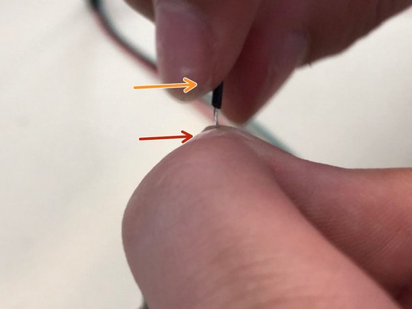
Pinch the exposed wire gently between thumb and finger.
-
Twist the jacket with the other hand. The wires will twist around each other to form a compact spiral.
-
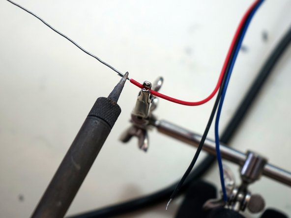
Melt some solder onto the exposed spiral end to fuse them together.
-
Avoid melting the protective sleeve.
-
Repeat this for all three wires wire of each switch.
-
-
-
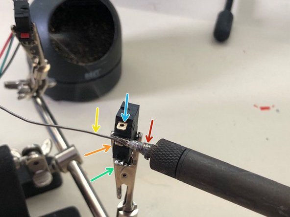
Bring the soldering iron (cleaner than shown!)...
-
...into contact with a leg of the switch and count two seconds.
-
touch the solder to both the iron and the leg. it should melt and leave a drop big enough to cover the hole in the leg.
-
It should look like this.
-
Do all three legs of both switches.
-
-
-
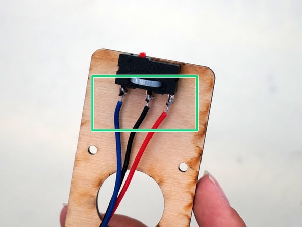
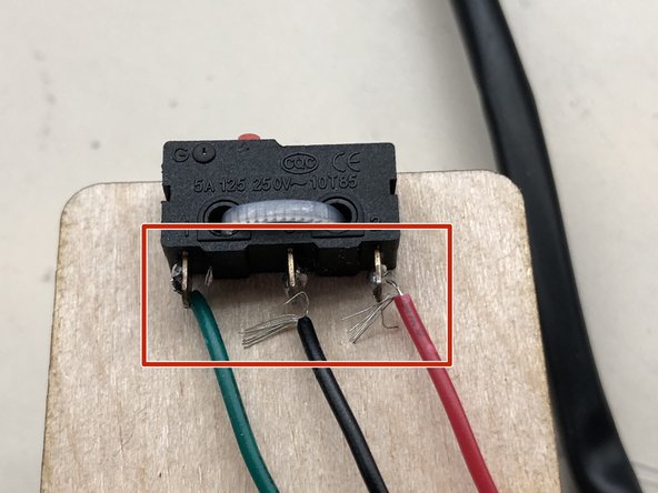
Pay special attention to the order of the colors when soldering.
-
Using the iron to melt the solder on both the switch leg and the wire, fuse them together. remove the iron and wait a moment for the solder to cool. This is an example of a good solder.
-
This is an example of BAD solder. Note the loose wires that were not twisted or pre tinned. This will break or short circuit very quickly.
-
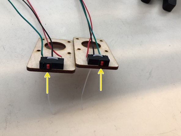
Once the wires are soldered, use a zip tie to attach each switch to the mounting plates. Trim the excess zip tie.
-
The switches MUST be mirror images of each other!
-
-
-
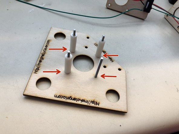
insert four M3x35 screws into the holes, flip the board over, and then put one 25mm spacer on each screw. This picture shows only three spacers on four screws.
-
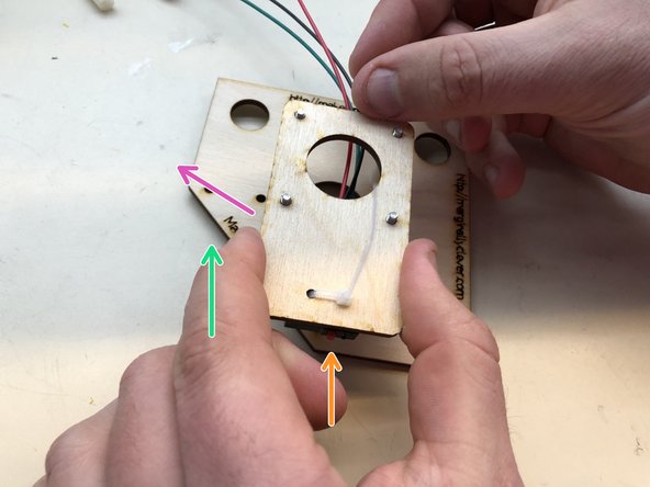
Mount the switch plate on top of the screws. The cables should come out along thie purple arrow, NOT go between the screws as this picture shows.
-
Remember the mirror images? If the diagonal part of the wood is on the left...
-
...then the switch must be on the right. On the other motor mount we will do things mirrored.
-
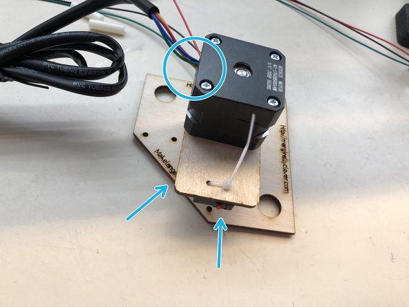
Put the motor on top of the switch plate. Not the direction of the wires coming out of the motor should be on the same side as the diagonal part.
-
-
-
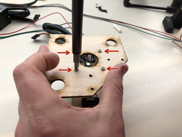
Carefully turn the assembly over and then tighten the four screws into the motor.
-
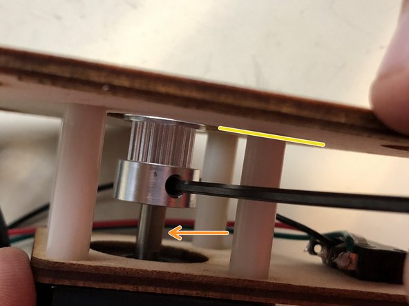
slide a GT2-20 pulley onto the motor shaft until the thin end is flush with the inside of the back plate.
-
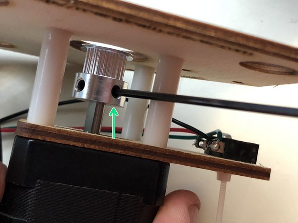
Use a size 2 metric alan key to tighten the set screw against the flat side of the motor shaft.
-
Tighten the second set screw for good measure.
-
-
-
Confirm motor wires are mirroring each other.
-
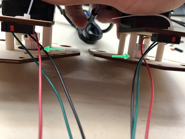
Confirm wires are outside the spacers
-
Confirm switches are mounted in the correct orientation.
-
Confirm the set screws are tightened against the flats and that the pulleys are at the correct height.
-
These picture are out of date and show green wires. In the newest version the green wire is blue.
-
-
-
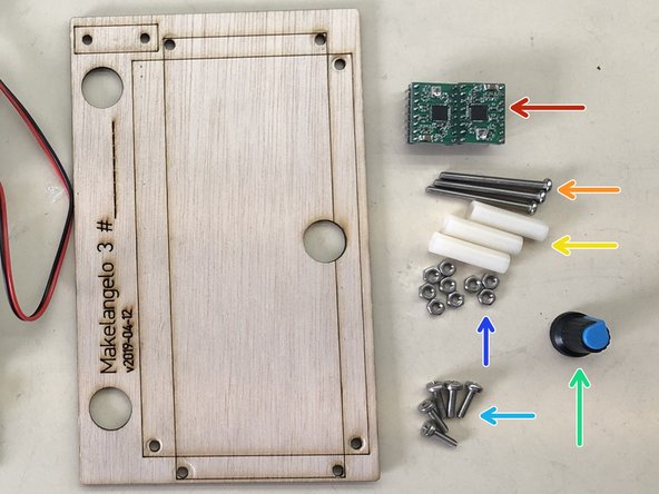
2x A4988 stepper drivers
-
3x M3x35 screws
-
3x 25mm spacers
-
9x M3 nuts
-
5x M3x10 screws
-
1x LCD panel knob
-
-
-
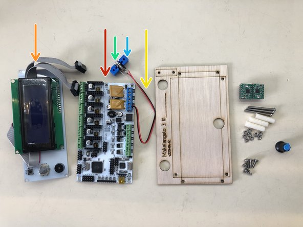
1x RUMBA board
-
1x LCD panel
-
1x 15cm pair of red/black wires
-
1x power connector
-
1x power connector mounting block (found in set of 3d printed parts for makelangelo)
-
1x 1m red/black/white servo extension cable
-
-
-
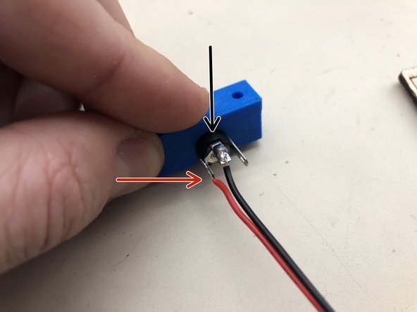
Solder the black wire to the north pole of the power connector following the same techniques used for the switches.
-
Solder the red wire to the west pole of the power connector following the same techniques used for the switches.
-
Leave the east pole unconnected. There is no south pole here.
-
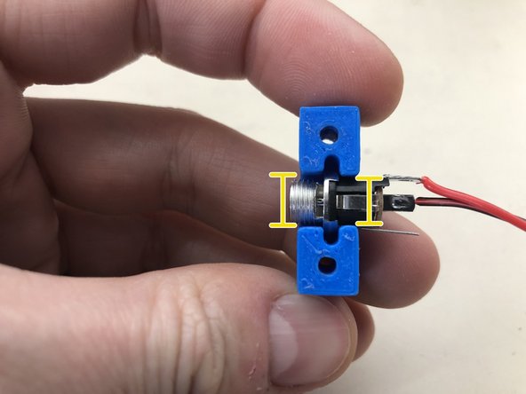
Press the socket into the mounting block. Note that one side of the block is slightly larger. The smaller side should be towards the wires.
-
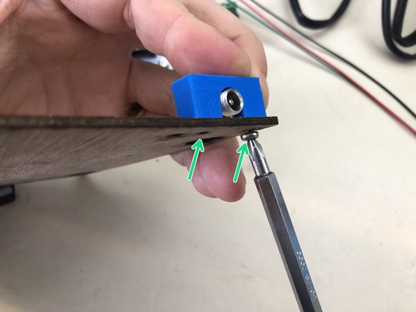
Screw the mounting block to the side of the control panel with two M3x10 screws.
-
Test the connection with a multimeter.
-
-
-
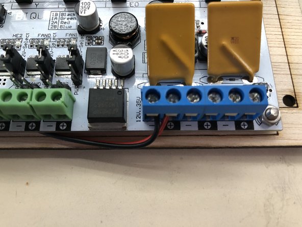
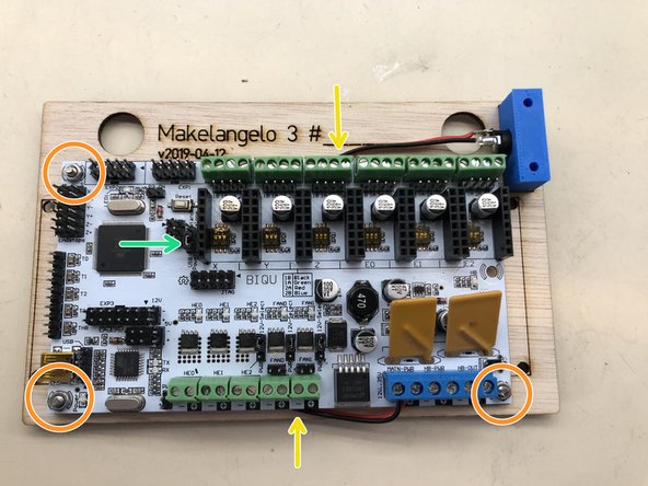
Strip the other end of the red/black wires and screw them into the terminal blocks as indicated. Note that red wire goes to the positive (+) terminal and black to the negative (-).
-
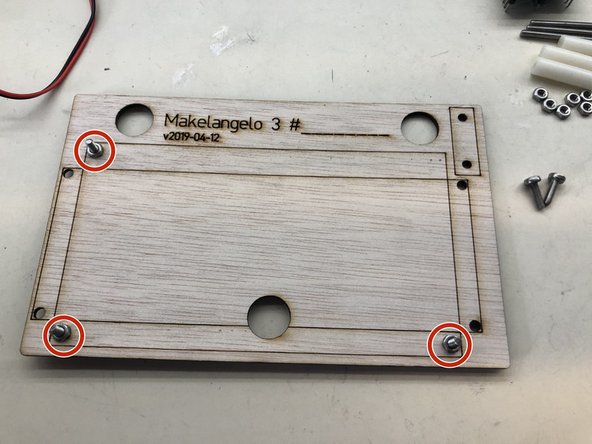
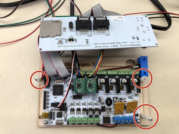
Insert three M3x10 screws in the marked holes and fasten them with one M3 nut each.
-
Place the PCB over the screws so that the power wire runs behind the PCB. Make sure that the wire does not stick out from the edge of the wood where it could get caught and pulled by an outside force
-
Secure the PCB with three M3 nuts.
-
Make sure the USB Power/Stand alone jumper is set to "stand alone"
-
-
-
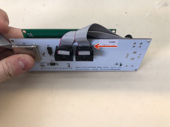
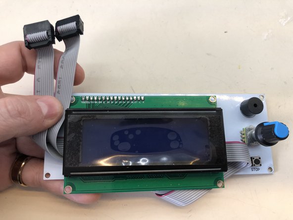
Attach the ribbon cables to the LCD panel. Note the orientation of the red line against the PCB.
-
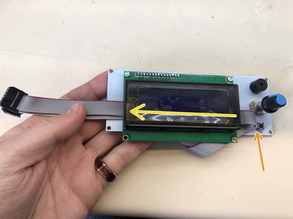
Fold over the cable...
-
...and gently fit it behind the LCD screen.
-
Attach the dial to the LCD panel
-
-
-
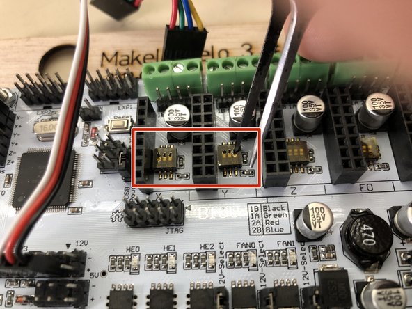
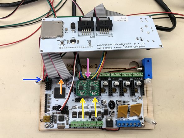
Press the DIP switches into the down position. The DIP switches are the yellow items under the gold colored tape.
-
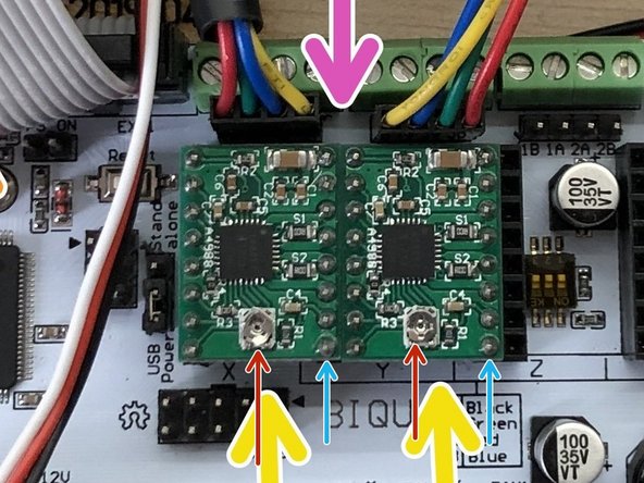
Press the stepper drivers into position. Note the orientation with the adjustment knob on the south side.
-
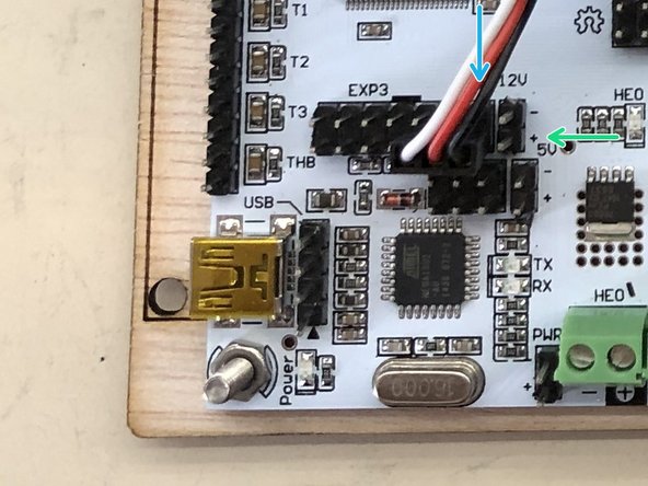
Attach the male end of the servo extension cable. Note how the black wire is on the south row, eastern-most pin of EXP3...
-
...and is NOT on the pair of 12v pins. On some models of RUMBA there are no 12v pins. Confusing! Be careful.
-
Attach the LCD cables to EXP1 and EXP2. Note the red wire on the west side.
-
Attach the motor mount switch wires (red/black/green) here. Note green is on the east side. The left motor connects to X-. The right motor to X+.
-
Attach the steppers. The left motor connects to the left set. Note the color of the wires: the yellow wires should be nearest to each other.
-
-
-
Connect power to the robot.
-
Get a multimeter. turn the dial to 20v resistance.
-
Put the red lead of the multimeter on the dial in the bottom center of the driver.
-
Put the black lead on the bottom right pin of the driver. The target value is 0.17
-
The dial MUST only be adjusted when the power is off or damage will occur.
-
Very small changes (5-10 degrees) are all that are needed to make big changes to the target value. The smallest (1-2mm) flathead screwdriver works great.
-
Turn power off, adjust the dial, turn power on, measure the value, repeat until within +/-0.05 of target.
-
-
-
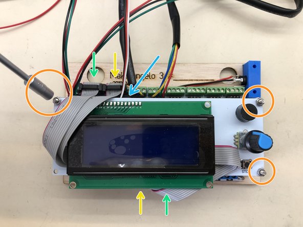
Insert three M3x35 screws and put one 25mm spacer on each.
-
Note the ribbon cables go to their corresponding color. Note the red edge and which way it is positioned.
-
Note the servo wire coming out the top.
-
Place the LCD onto the screws and secure in place with three M3 nuts.
-
Congratulations! The Makelangelo 3 is now assembled. You will still need a pen holder and upload firmware, both found in separate tutorials.
Congratulations! The Makelangelo 3 is now assembled. You will still need a pen holder and upload firmware, both found in separate tutorials.
Cancel: I did not complete this guide.
2 other people completed this guide.
![[old] Makelangelo 3.3 construction](https://d3t0tbmlie281e.cloudfront.net/igi/mcr/sKBaALJBLOYOanLi.medium)


