Difficulty
Moderate
Steps
12
Time Required
- 4. Elbow Tail and Ulna Assembly 12 steps

In Progress
This guide is currently being written. Reload periodically to see the latest changes.

Private
This guide will not appear in search results and can only be viewed by team members!
Quiz
0
-
-
Package #4
-
Ulna Gearbox portion of Package #5
-
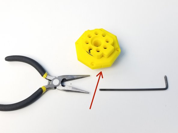
Alan Keys
-
Socket Drivers
-
Needle Nose Plier
-
-
-
Prepare the following components:
-
5B - Eccentric Cams
-
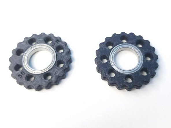
5B - Top and Bottom Rotors
-
3/8'x396.35mm Brass Tube
-
15x21x4mm 6702 Bearing (x3)
-
M3x4mm Set Screw (x3)
-
-
-
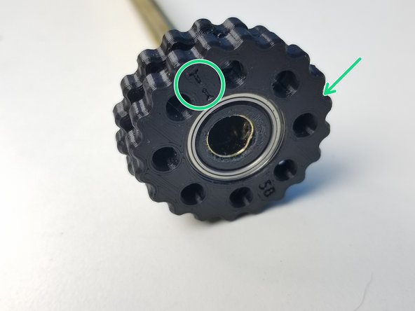
Insert the 6702 Bearings in the Rotors
-
Make sure the Bearing is all the way in.
-
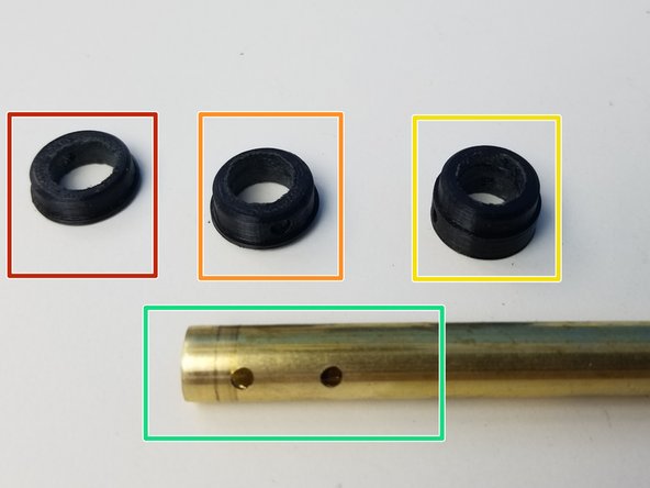
Prepare the Cams and Brass Tube that acts as the input shaft
-
Top Eccentric Cam (thinnest profile)
-
Bottom Eccentric Cam (medium profile)
-
Concentric Cam (thickest profile)
-
Machined Brass Tube, 3 hole drilled end
-
-
-
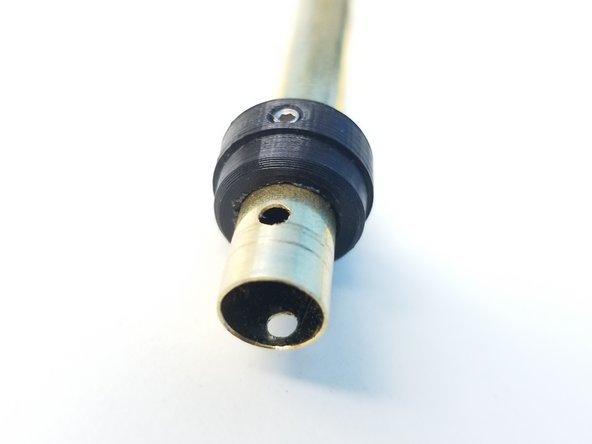
Insert and align the Concentric Cam's Set Screw hole to the furthest of 3 holes on the brass tube and secure it using a M3 Set Screw
-
Do NOT screw further than you have to. You want to make sure the screw has bit into the Brass Tube Hole but no deeper than that.
-
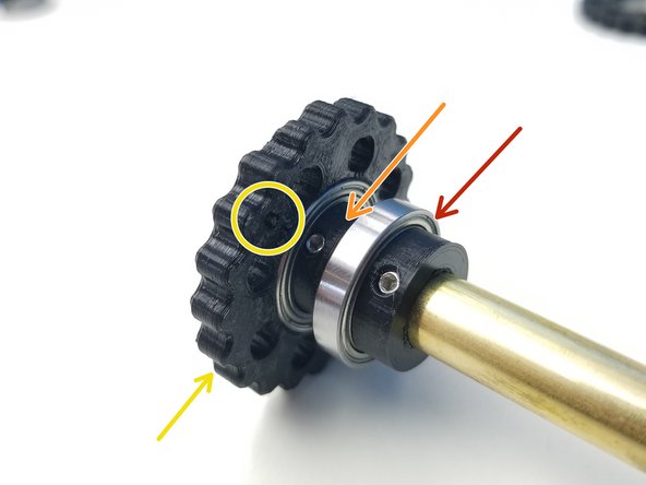
Place the 6702 Bearing
-
Repeat the above process with the Bottom Eccentric Cam (medium thickness)
-
Insert the "B" Rotor, once the Set Screw in secured just enough for the bearing to go in.
-
Repeat the Orange and Yellow steps with the Top Eccentric Cam (thinnest profile) and "T" Rotor
-
-
-
Prepare the following components:
-
5Bc - Ulna Housing Top parts
-
5Bd - Output Disks
-
30x37x4mm 6706 Bearing
-
M3x25mm Screws (x8)
-
M3 Hex Nuts (x8)
-
-
-
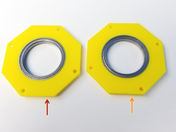
Insert 6706 Bearings into 2 Top Housing parts
-
Top output disk housing (chamfered on one side)
-
Bottom output disk housing (not chamfered)
-
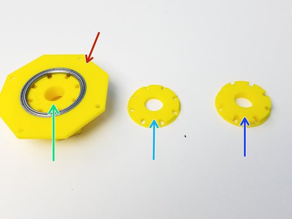
Prepare the Output disks with the Top Output Disk inserted on the Chamfered side of the Top Output disk
-
Top Output Disk (Thick Cross)
-
Middle Output Disk (Thinnest disk)
-
Bottom Output Disk (Medium Thickness disk)
-
-
-
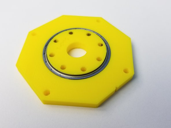
Place the Middle Output Disk on the other side of the Top Output Housing
-
Use the M3x25mm screws to Hold them in place
-
Insert the Bottom Output Disk on the Bottom Output Housing
-
Make sure to look down on the non label face of the Output Housing when inserting the Bottom Output Disk
-
-
-
Screw in all the M3x25mm screws
-
Align the 2 Output Housing and use Needle Nose Pliers to tighten the nuts
-
-
-
Prepare the following components:
-
5Ba-b - Housing Parts
-
Previously assembled Parts (Input shaft and Output disk
-
M3x5mm Screws (x8)
-
M3x25mm Screws (x2)
-
M3x35mm Screws (x4)
-
M3 Hex Nuts (x6)
-
M3 Square Nuts (x8)
-
-
-
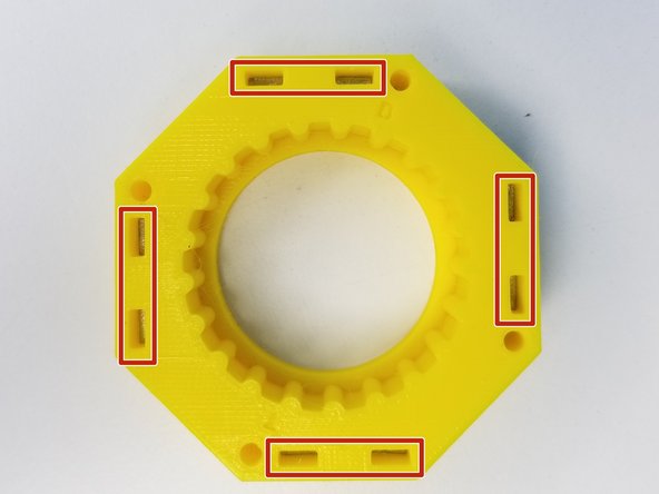
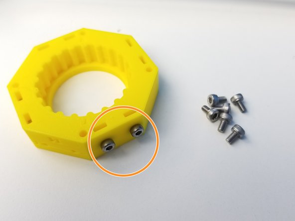
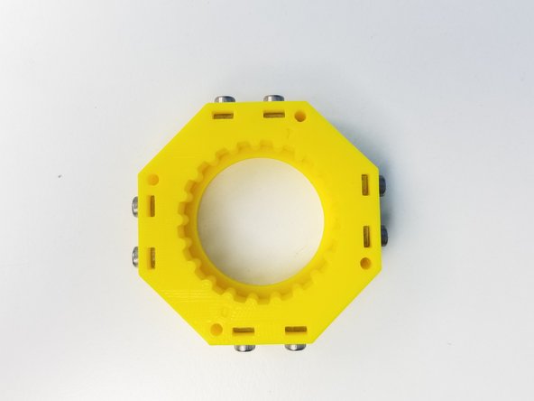
Insert Square Nuts on the 5Bb Rotor Housing parts
-
Use M3x5mm Screws to hold these square nuts
-
These nuts are future Cable Management attachment depending on the Tool that's attached at the end effector
-
-
-
Align the "T" Labels on the rotor to the Rotor Housing and insert only the Top Rotor
-
Align the "B" Labels on the rotor to the Rotor Housing and insert it through.
-
Clamp the Bottom Housing parts on the Concentric Cam Bearing using the M3x25mm Screws
-
-
-
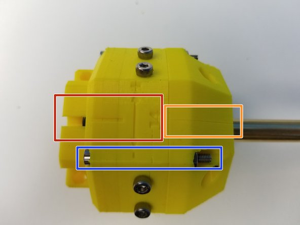
Align the Output Disk Housing and the Rotor Housing to the Alignment Line
-
Align the Bottom Housing parts in a way that the separation line is aligned to the label
-
Screw the Housing components using the M3x35mm Screws
-