-
-
Package #6
-
Alan Keys
-
Needle Nose Plier
-
-
-
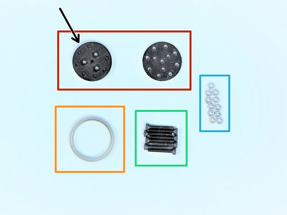
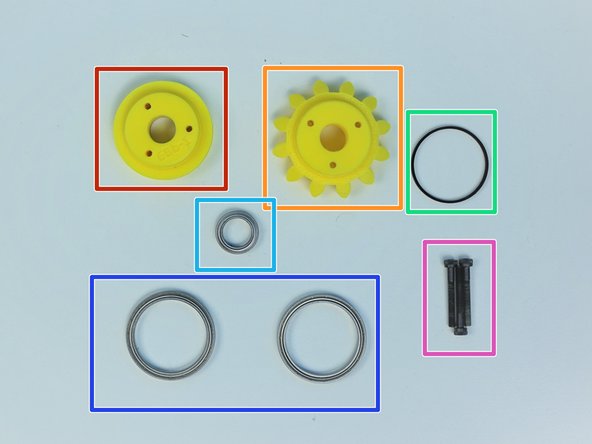
Prepare the following components:
-
[3D] - 6Da Hand GB Rotors
-
[3D] - 6Da Hand GB Eccentric Cams
-
[3D] - 6Db Hand GB Bevel Gear
-
Brass Tube [5/16' x 19.5mm]
-
6701 Bearing [12x18x4mm] (x4)
-
M3x4mm SetScrew (x3)
-
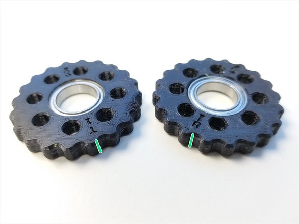
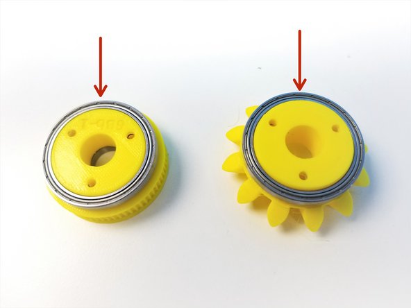
Rotors are Labelled "T" and "B" for Top and Bottom according to Eccentric Cams' Top and Bottom, Thick Piece = Bottom and Thin Piece = Top
-
-
-
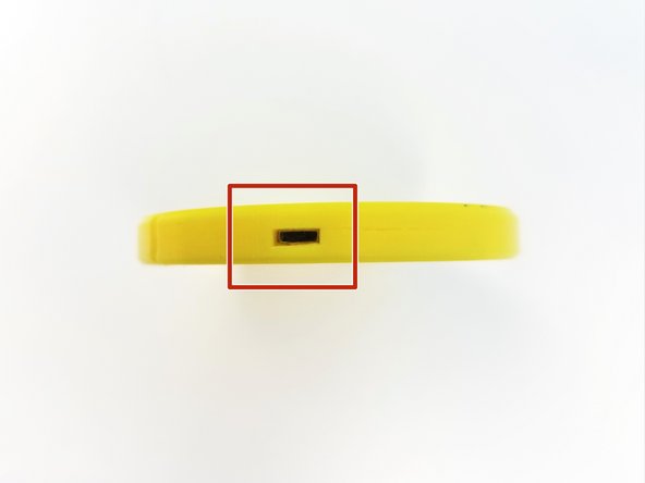
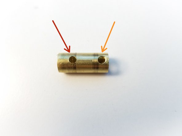
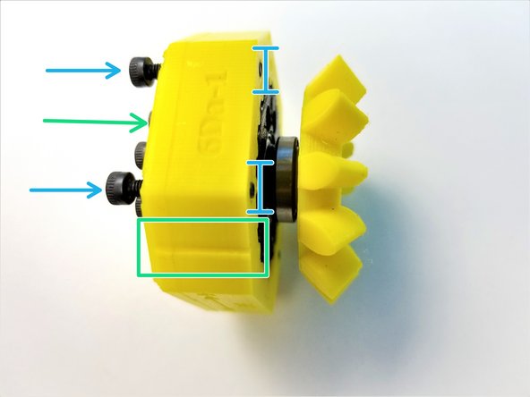
Brass Tube has one side that has 2 holes
-
Furthest away from the edge is for Bevel Gear Set Screw
-
Closest to the right edge is for Top Eccentric Cam Set Screw
-
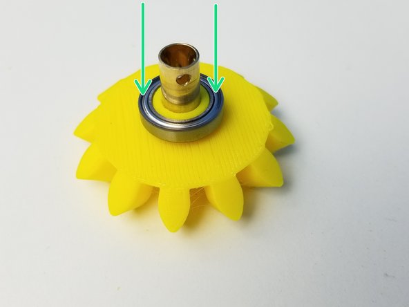
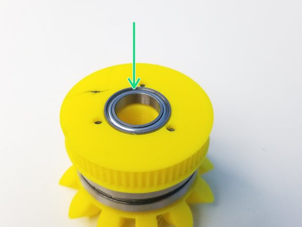
Insert 6701 Bearing in the Bevel Gear
-
-
-
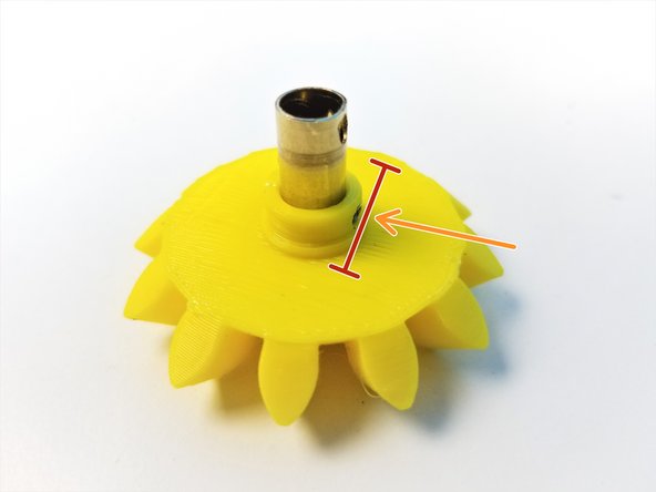
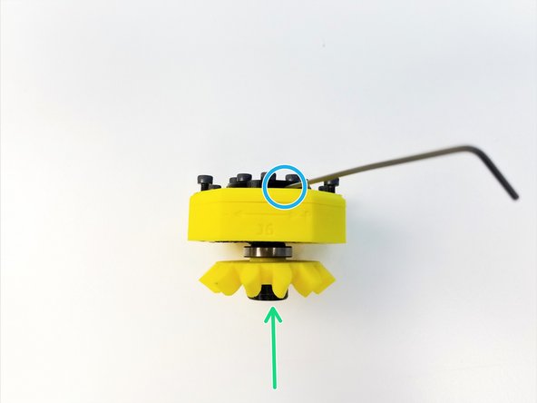
Align the Brass Tube Hole to the Bevel Gear Set Screw Hole
-
Secure the Gear using M3 Set Screw
-
Make sure the Set Screw goes in just enough for the bearing to go on, NO MORE THAN THAT
-
Slide the 6701 Bearing over the Set Screw Hole on Bevel Gear
-
-
-
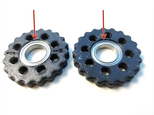
Insert 6701 Bearings into each Rotor. Make sure they are fully inserted
-
Make a sharpie mark on the side of the Rotors along the "T" and "B" label. This will help the alignment process in the future.
-
-
-
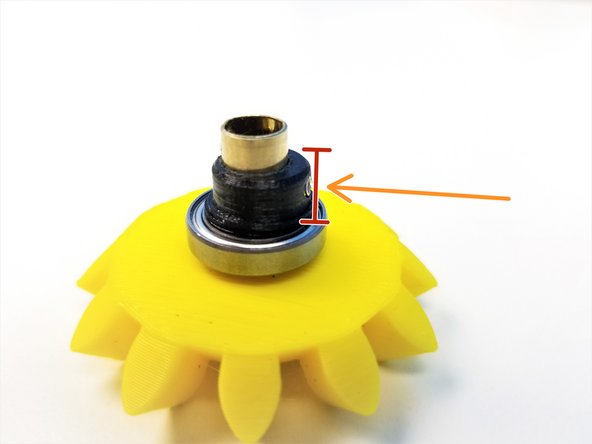
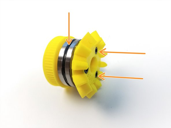
Align the Thick Eccentric Cam {Bottom} and use the M3 Set Screw to secure its location
-
Make sure the Set Screw goes in just enough for the bearing to slide over NO MORE!!
-
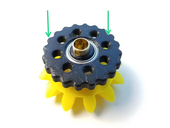
Place the "B" Rotor onto the eccentric cam with the "B" label facing the Bevel Gear
-
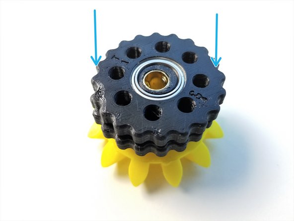
Repeat with the Thin Eccentric Cam {Top} and "T" Rotor with "T" label facing up
-
-
-
Prepare the following components:
-
[3D] - 6Da Hand GB Output Disks
-
Thicker Output Disk is considered "Top"
-
6706 Bearing [30x37x4mm] (x1)
-
M3x20mm Screws (x8)
-
M3 Hex Nuts (x11)
-
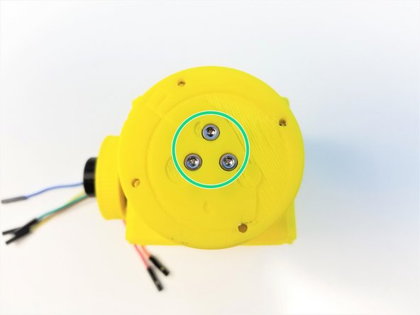
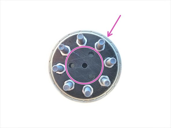
Insert M3 Hex Nuts in the nut inserts of Both Output Disks
-
Align the 3 middle holes of Top and Bottom Disks. Clamp the 6706 bearing with the Output Disks using M3x20mm Screws
-
-
-
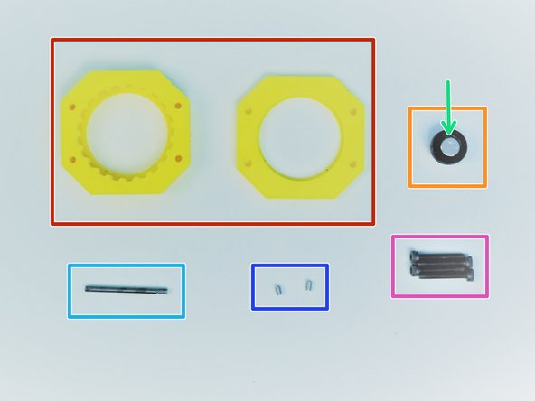
Prepare the following components:
-
[3D] - 6Da Hand GB Housing {Top & Bottom}
-
[3D] - 6Da Hand GB Magnet Holder
-
8x2.5mm Neodymium Magnet
-
M3x35mm Threaded Rod
-
Since February 2020, this is replaced with Brass Tube [1/8'x35mm]
-
M3x4mm Set Screws (x2)
-
M3x20mm Screws (x4)
-
-
-
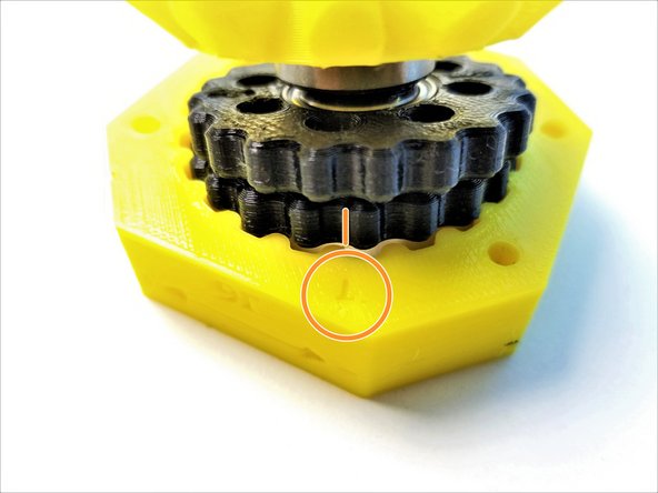
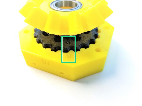
Rotor Alignment is very IMPORTANT! Follow the pictures carefully!
-
Make sure there are sharpie marks on the side of the Rotors where it lines up with "T" and "B" on the rotors
-
Align the Side Mark of "T" Rotor to the "T" on the Housing, and only insert Top Rotor into the housing.
-
Align the Side Mark of "B" Rotor to the "B" on the Housing, and insert the Bottom Rotor
-
When aligned properly all 8 holes made by 2 rotors intersecting should have equal spacing
-
-
-
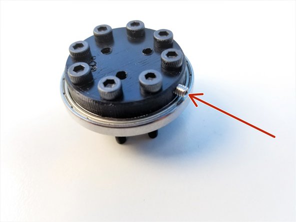
Insert M3 Set Screw on the side of the Output disk
-
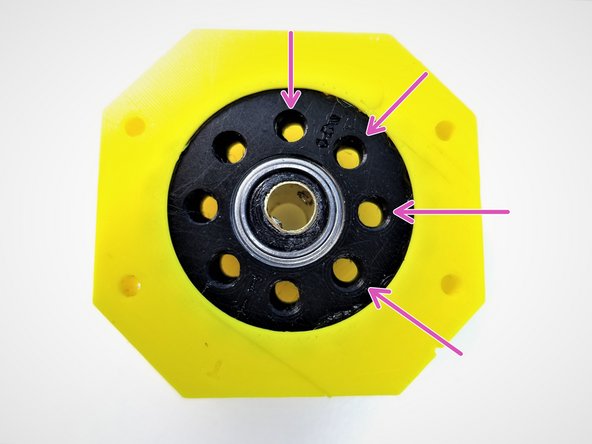
Insert the Assembled Output Disk pins through the Rotors
-
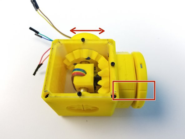
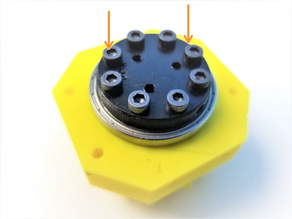
Slide in the Top Housing to 6706 Bearings on the Output Disk and align the Top & Main Housings along the alignment markers
-
Secure its position using M3x20mm Screws. ONLY screw in until it's flushed to the face of the housing
-
-
-
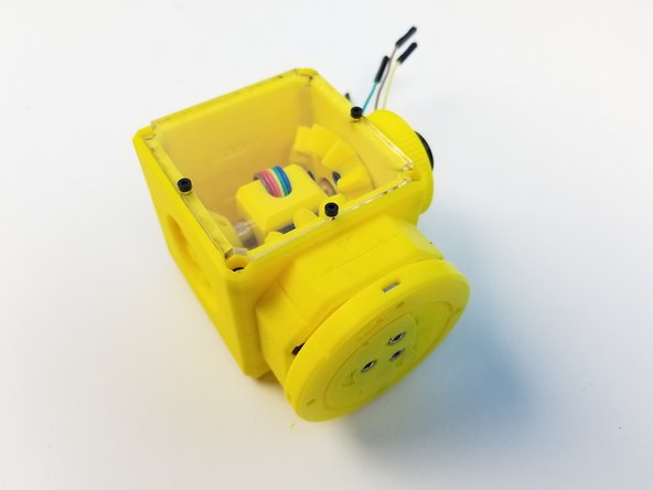
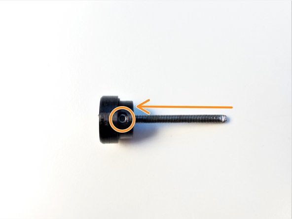
Insert the Neodymium Magnet in the Hand Sensor Magnet Holder, if you haven't yet.
-
Insert M3 Threaded Rod in the Magnet Holder. Secure the Rod using the M3 Set Screw
-
Feed the other end of the Rod to through the Input Shaft Tube all the way to Output Disk
-
Secure that end with a M3 Set Screw in the Output Disk
-
-
-
Prepare the following parts:
-
[3D] - 6PI Pulley Gear
-
[3D] - 6Ba Bevel Gear
-
[3D] - 6Bc Bearing Spacer
-
6701 Bearing [12x18x4mm] (x1)
-
6706 Bearing [30x37x4mm] (x2)
-
M3x25mm Screws (x3)
-
-
-
Slide in 6706 Bearings on the Pulley and Bevel Gear
-
Clamp the Bearing Spacer between the Pulley and the Bevel Gear using M3x25mm Screws
-
Insert the 6701 Bearing in the Pulley Gear
-
-
-
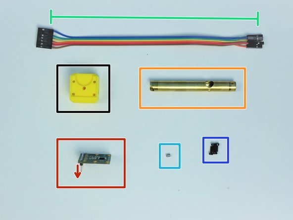
Prepare the following parts
-
[3D] - 6Ae Hand Sensor Holder
-
AS5147 Sensor {straight header on the label side}
-
Brass Tube [3/8'x76.5mm]
-
6-pin Ribbon Cable F/F - Brown to Blue {sensor 5 Hand Ext.} - [210mm]
-
M3x4mm Set Screws (x1)
-
M2x6mm Screws (x4)
-
-
-
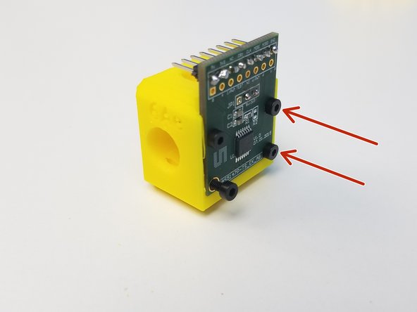
Mount the AS5147 Sensor on the Sensor Holder using the M2 Screws
-
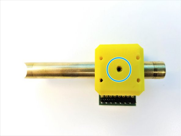
Alignment of the Brass Tube is important!!
-
Moon Cut is facing away from the Sensor Chip
-
Sensor Cable Hole is away from the Headers
-
Insert the Brass Tube through the Sensor Holder Use M3 Set Screw to secure the Sensor Holder
-
-
-
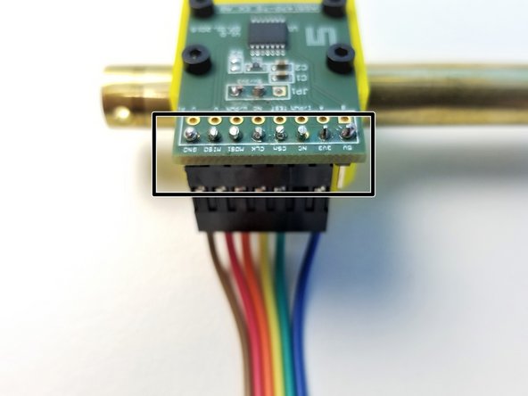
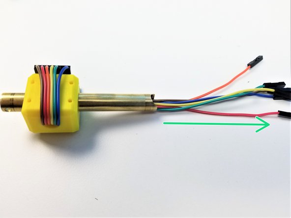
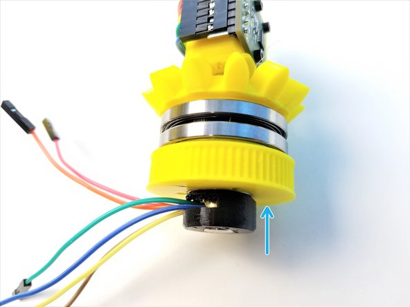
Connect the Cable to the AS5147 Sensor as shown in the picture
-
COLOR CODE MATTERS!!
-
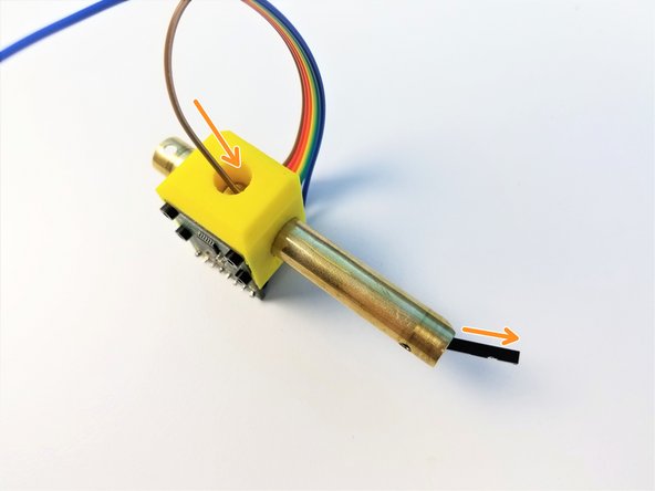
One wire at a time, feed the jumper wires through the Brass Tube
-
Make sure the Jumper Wires comes out of the Brass Tube as far as it can. NO LOOSE Cables
-
-
-
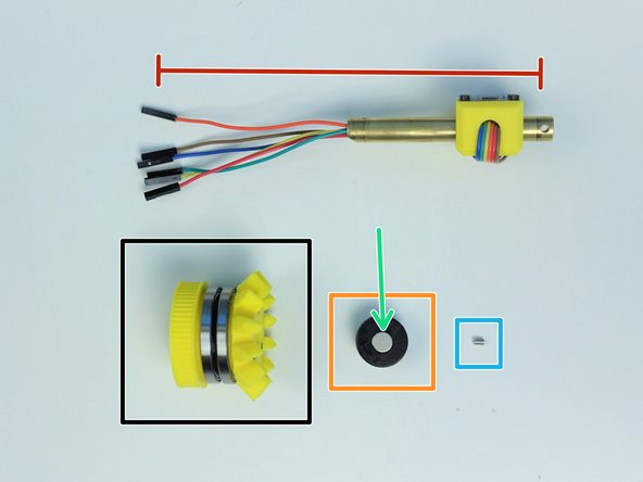
Prepare the following components:
-
Assembled Side Bevel Gear
-
Assembled Sensor Shaft
-
[3D] - 6Mc Picasso Magnet Holder
-
8x2.5mm Neodymium Magnet (x1)
-
M3x4mm Set Screw (x1)
-
-
-
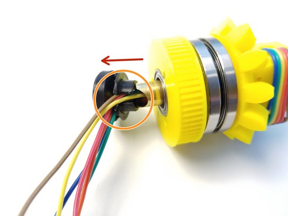
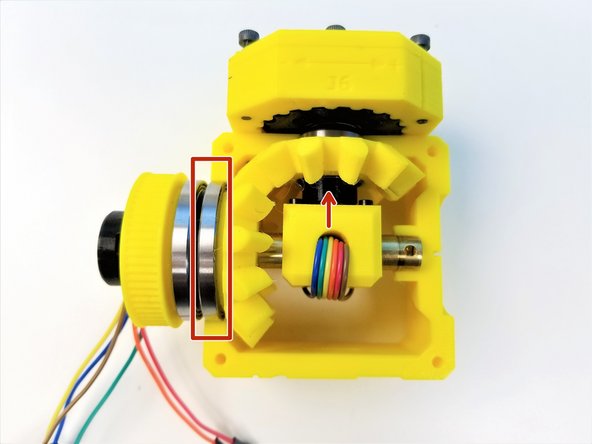
Insert the the cable end of the Brass Tube {Sensor Shaft} through the Assembled Side Bevel Gear
-
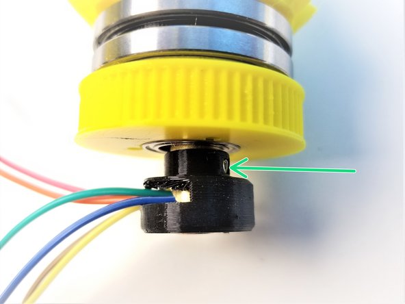
Insert Picasso Magnet Holder on the Brass Tube and align the set screw holes
-
When aligned properly, "Half Moon Cut" on the Brass Tube should line up with the opening on the Magnet Holder
-
Secure the Magnet Holder using M3 Set Screw
-
Push the Magnet Holder into the 6701 Bearing that's in the Pulley Gear
-
-
-
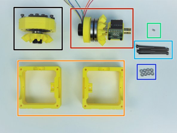
Prepare the following components:
-
Assembled Hand Gearbox
-
Assembled Side Bevel Gearbox and Sensor Holder
-
[3D] - Picasso Box {Top = 6Aa & Bottom = 6Ab}
-
M3x4mm Set Screws (x1)
-
M3x45mm Screws (x4)
-
M3 Hex Nuts (x8)
-
-
-
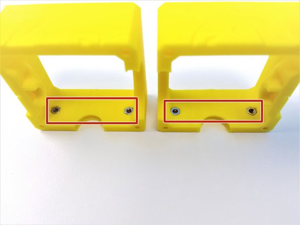
Insert M3 Nuts on both Picasso Box Parts
-
Insert 6701 Bearing of the Hand Gearbox into the small bearing insert of the 6Aa Picasso Box
-
Secure the Hand Gearbox using the M3x20mm Screws
-
-
-
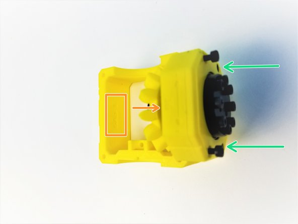
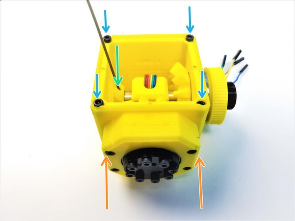
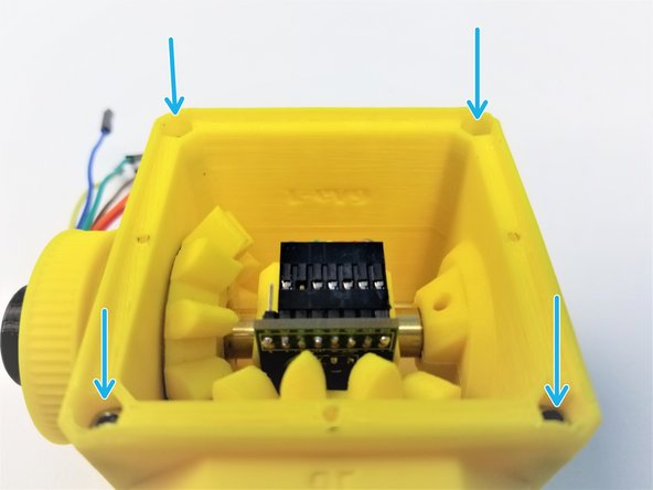
Align the 6706 Bearing closer to Bevel Gear to the Picasso bearing insert of 6Aa Picasso
-
Hand Sensor Chip should be facing the Hand Gearbox
-
Clamp the 6Ab Picasso and secure it by tightening the M3x20mm Screws on the Hand Gearbox
-
Use M3 Set Screw to secure the Sensor Shaft to the Picasso Box
-
Insert M3x45mm Screws on one side and M3 Nuts on the other, to clamp the Picasso Box
-
-
-
Hold the picasso box with one hand and turn the input pulley of the Side Bevel Gearbox with the other.
-
The input pulley and the hand should turn smoothly at different ratios, with little or no play.
-
If the gearbox refuses to turn, it is very likely the 3D printed gears are too tight. Now is the time to reprint them before continuing with assembly.
-
-
-
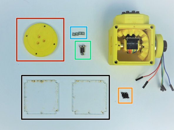
Prepare the following parts:
-
[LSR] - Acrylic Picasso Cover Plates (x2)
-
[3D] - 6Da Hand Face
-
M2x6mm Screws (x6)
-
M3x10mm Screws (x3)
-
M3 Square Nuts (x4)
-
Screw the Acrylic Plates to Top AND Bottom of Picasso Box with M2 Screws
-
-
-
Insert M3 Square Nuts on the side of the Hand Face
-
Align the Screw Hole on the ++Hand Gearbox Output and Hand Face++
-
One of three holes are in between the Screw Head
-
Secure the Face to the Output Disk using M3x10mm Screws
-
-
-
Align the Hand Face to the Hand Gearbox Housing by rotating the Pulley Gear
-
Congratulation! you have your Picasso Box assembled!!!
-


![[3D] - 6Da Hand GB Rotors](https://d3t0tbmlie281e.cloudfront.net/igi/mcr/n3COSDCEKQAQoyay.medium)


![[3D] - 6Da Hand GB Output Disks](https://d3t0tbmlie281e.cloudfront.net/igi/mcr/Cet3v2ALMRJe34OT.medium)


![[LSR] - Acrylic Picasso Cover Plates (x2)](https://d3t0tbmlie281e.cloudfront.net/igi/mcr/VGwVcvnvAJBplXtL.medium)