Introduction
Now that your pen holder is done you're ready to mount your Makelangelo 5 (or mount your Makelangelo HUGE) and run the Makelangelo software.
-
-
This guide will show you how to assemble a Makelangelo pen holder, 2023 edition.
-
-
-
The black timing belt goes through the flat disc with the rectangular hole, then is pressed into the bolt clip.
-
Notice how the belt if fitted to the last notch of the bolt holder. This is important to ensure accuracy. It is OK to press the bolt holder against a hard surface to get the belt fully seated in the gap.
-
Click the bolt into the bolt holder.
-
Note how the hole in the switch disc is rectangular. Press the switch disc onto the bolt holder with the long side touching the belt. It should be a snug fit.
-
-
-
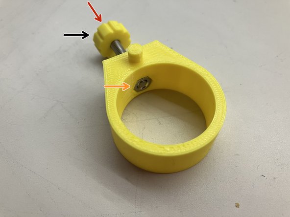
Put the knob on the M4 screw.
-
Start twisting the M4 screw into the one-way ring.
-
Press the M4 nut into the hex-shaped hole on the inside of the one-way ring. If the fit is too tight try turning the screw until the nut is pulled into the hole.
-
It is important that the nut and the tip of the screw be flush with the plastic for the next assembly step.
-
-
-
Press one stabilizing ring onto each each hand of the arm. They should be a snug fit.
-
If they are not a snug fit, try adding a single layer of tape to increase the friction.
-
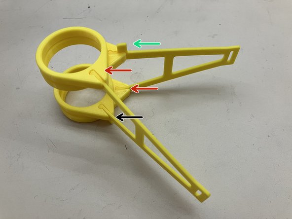
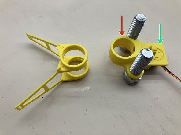
Assemble both sets of arms as shown. Note how one arm is flipped over so they are face-to-face.
-
Also note the direction and position of the tab.
-
-
-
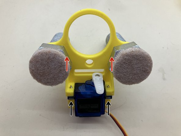
Use the screws from the servo kit to attach the servo to the main body.
-
Screw the M16x50 bolts into the main body. Try to orient the flat sides of the heads as shown. It is a very snug fit. It may require pliers or an adjustable wrench.
-
The pads in this photo are optional. Your mileage may vary depending on the type of art you will create.
-
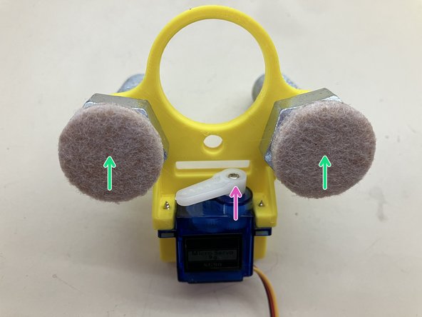
The plastic gears of the servo wear out easily and can be broken with too much force. Avoid turning the horn by hand.
-
-
-
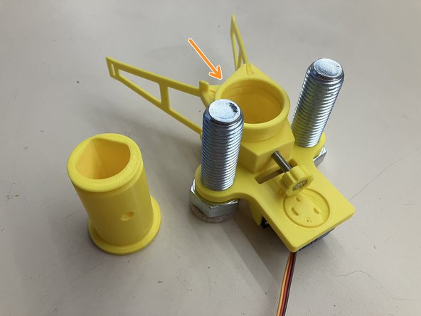
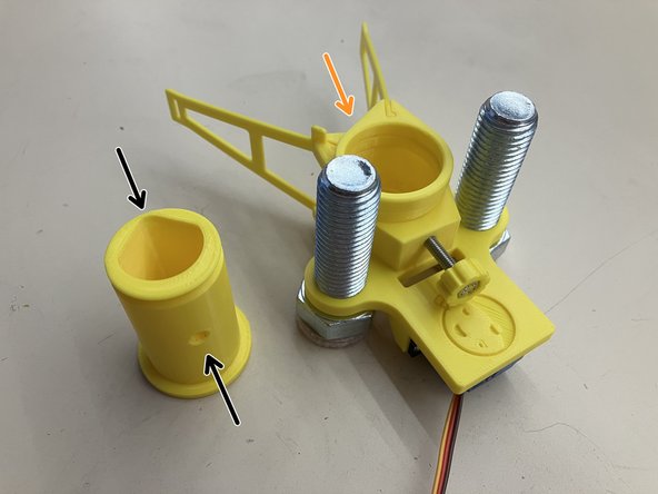
Stack the one way ring (the part with the M4 screw)...
-
...onto the main body so they fit together. The hole on the main body matches the bump on the one-way ring. There should be no gap between the parts.
-
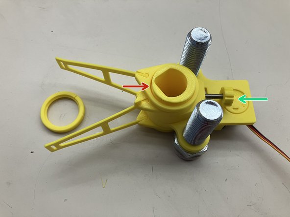
Fit the arm pair around the main body assembly. One half of the pair is under the main body. One half is above the one-way ring.
-
-
-
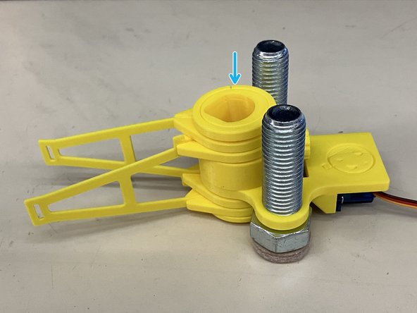
Note the shape at the end of the collet and the location of the screw hole. The M4 screw will pass through the hole.
-
Arrange the collet with the wide part on the bottom. Lift the rest of the assembly as one and lower it on to the collet.
-
Rotate the collet so that the top of the teardrop shape is away from the M4 screw.
-
Tighten the M4 screw to secure the assembly together. It may be necessary to adjust the collet vertically or by rotating so that the screw passes through the hole. If you feel the screw resistance increase then you are not lined up correctly.
-
Attach the retaining snap ring on the end of the collet.
-
-
-
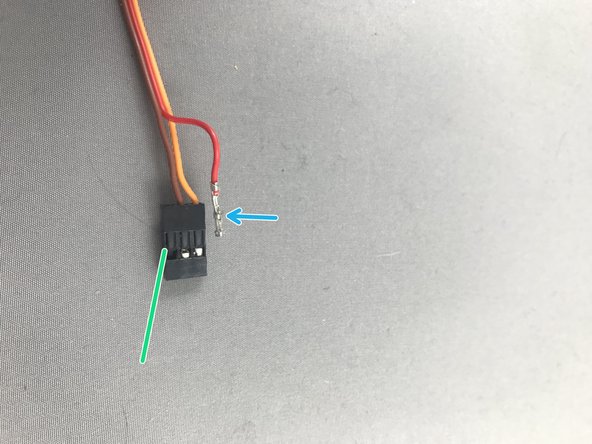
The Servo is the little blue motor on the pen holder. The servo cables wires must be in this order: Orange, Brown, Red. Always check the position of new servo cables before running Makelangelo. If the servo is connected without being swapped the Makelangelo will not power on. Marginally Clever swaps new servos when they test each one.
-
While gently pulling on the red wire, slide a pin under the hook of the black JST header to carefully lift and release the crimp pin. When you get it right the crimp pin will slide out effortlessly. Lifting too hard can break the hook so be gentle!
-
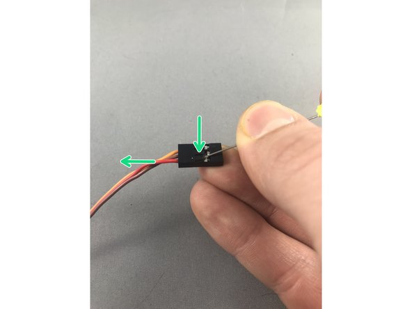
Note which side is up on the pin - there is a tong that catches on the hook.
-
Once both crimp pins are released, reinsert them with the new order. Be sure to keep the tong on the up side to catch on the hook.
-
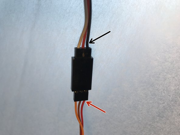
Remember: when connecting the servo to the extension cable, the red wire of the servo goes to the black wire of the extension cable.
-