-
-
The 3D View can be found via the Windows menu. The keyboard shortcut is Shift+F1
-
3D View may be open already in a tab. Look for the matching tab name.
-
Change active camera in the Scene with the 3D view > camera selector. There is always a default Camera 1
-
Render: Activate render passes. Each render pass draws one type of thing the camera might see in the 3D view. They can be set to Never, Sometimes, or Always.
-
Copy to Scene: Makes a copy of the active camera and adds it to the root of the Scene. Here a camera has been added and renamed by the user.
-
-
-
Toggle Select
-
...then double click items in the scene.
-
The selection change will affect several tabs.
-
Toggle Move and the move gizmo will appear at the center of the selected item. If you have many things selected it will appear at the center of the last item.
-
Click and drag the spheres to move in a straight line. Click and drag the squares to drag in the plane.
-
Toggle Rotate to get the rotate gizmo. Click and drag the boxes to rotate. The white lines snap to 5, 10, and 45 degrees.
-
Click the globe to change the frame of reference. The two frames available are World (globe) and Local (eye). Local is the frame of reference of the last selected item.
-
-
-
Pan and tilt: Drag the mouse while holding the middle mouse button.
-
Dolly: Drag the mouse while holding the middle mouse button and SHIFT.
-
Pedestal and Truck: Drag the mouse while holding the right mouse button and SHIFT.
-
Orbit: Drag the mouse while holding the right mouse button. Change the orbit distance by rolling the mouse wheel.
-
As you get closer to the orbit point your movements will be come smaller.
-
You can also adjust the mouse sensitivity in File >Settings > Viewport
-
-
-
Did you know? You can see one camera from another. Add a second camera and try it!
-
Make sure Render > Cameras is set to Always or else the cameras will be invisible.
-
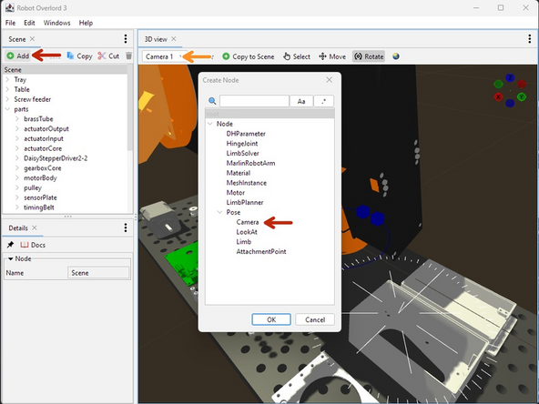
Use the Scene > Add > Pose > Camera. The new camera will appear in the Scene graph under the selected nodes. A ray coming out of the camera shows the relationship between your cursor and the 3D world.
-
In 3D View, select the new Camera. The view will now draw from the new point of view.
-
Move one camera until it is pointing at the other camera.
-
-
-
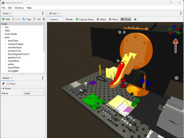
The Compass appears in the top right of the view.
-
The handles with letters are the positive direction of each axis. The handles without are the negative.
-
Hover the cursor over the compass and the background will change. Hover the cursor over a handle. The letter will appear in white.
-
Click the mouse on each handle to make the camera orbit to face that direction.
-
-
-
Get the HelloWorld.zip or any of the adjacent examples
-
Unzip the helloWorld file. It will create a helloWorld folder.
-
Run RO3 and select File > Load Scene.
-
Locate your helloWorld folder.
-
Select helloWorld.ro
-
and hit Open.
-
New nodes should appear in the Scene panel
-
The Sixi 3 robot arm will appear in the 3D view
-
-
-
In the Scene panel, Click on MarlinRobotArm to make it the subject of the Detail panel.
-
Notice the target node. This is where the position and rotation that the arm End Effector wants to match.
-
Pay special attention to the z axis (blue line) of the target. The z axis is always facing out from the wrist of the arm. Want the arm to point down? Make the target z axis point down.
-
Move the linear velocity slider. Left is zero. More right is faster.
-
-
-
In the Scene panel, Click on target to make it the subject of the Detail panel. Change the numbers to translate and rotate the target.
-
In the 3D View select Move. A gizmo will appear on screen. Grab with the left mouse and slide to move the target. The arm will follow as though it is attached with a rubber band.
-
In the 3D View select Rotate. The gismo will change. Grab the handles to rotate the target. The robot wrist will turn to try and match angles.
-
Did you know? As the camera gets closer to the target, the movements made by the cursor will be smaller. Need more precision? Get close.
-
-
-
In the Editor panel, click the ... selector.
-
Choose the MarlinRobotArm. The selector will not let you select the wrong type.
-
Click OK to confirm. Now the Editor knows with whom it is working.
-
Turn on Get: The next message from the robot arm will be written at the cursor position of the Editor panel. When a message is received Get will turn off.
-
Turn on Lock: Locks Get on until the lock is released.
-
Messages can be triggered by sending Gcode commands. Some examples include G0, G1, and M114.
-
Messages can also be sent from the Editor panel. Click Send and the current line of text at the cursor position will be sent to the selected robot.
-
By combining Get+Lock+G0, you can then move the arm to many positions and hit Send at each one to build up a sequence of moves.
-
-
-
Make sure the robot is designed with the base of the arm at the world origin. The Z axis (blue) should be up. The X axis (red) should be forward.
-
Make sure there is one Component for each moving section of the arm and the base.
-
Hide any internal components. This protects your design secrets and makes the file run smoother.
-
Export each component separately.
-
Set the Format to OBJ.
-
Set the Unit Type to centimeters.
-
Export it to a folder on your computer.
-
-
-
The easiest way is to modify an existing robot arm. Here we will start by loading the Meca500 example.
-
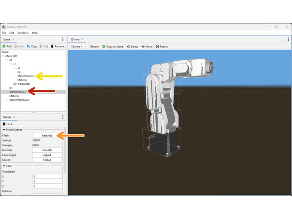
In the Scene tab, find the first MeshInstance for the base.
-
In the Details tab, click on the Mesh button and choose your OBJ file.
-
If your model file appears turned the wrong way or the wrong size, you will have to export it again from Fusion360.
-
Repeat for all subsequent MeshInstances.
-
Your mesh files might appear in the wrong position. We will fix them in the next step.
-
Your arm should look like this. The colors are all wrong but the meshes should be in the right place. We will fix the colors in the next step.
-
-
-
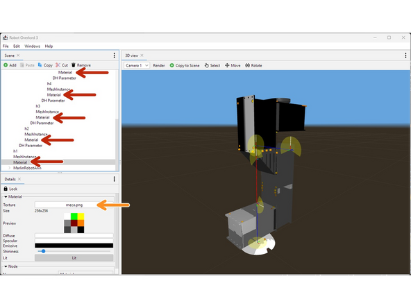
The example file already has some Material settings. These were meant to paint the Meca500 model, not your new design. You will need to change these settings for your arm. Symptoms include incorrect colors or missing parts.
-
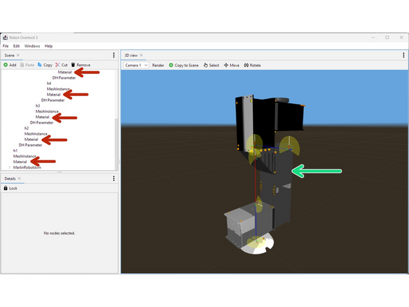
In the Scene tab next to each MeshInstance there is a Material node.
-
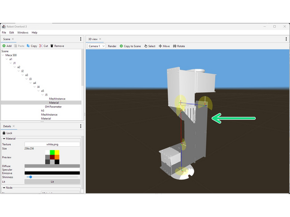
Change the Texture of the Material to your new texture. A white square 64x64 is a good option.
-
Your robot should look like this. Notice that the DH parameters are very different from the mesh and moving the arm will look very wrong. We fix that in the next step.
-
Drawing DH parameters and Hinges can be turned on and off in the 3D view tab render menu.
-
-
-
The DH parameters will be wildly different from your new model.
-
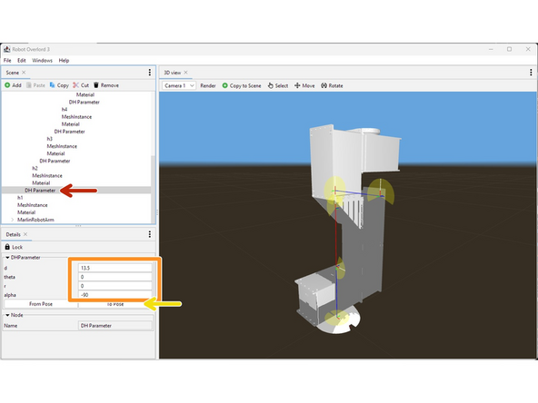
Starting from the first joint, locate the DHParameter node.
-
Adjust the d, theta, r, alpha values to match your new robot arm. You will see the blue and red lines change.
-
The sequence of moves is always translate along z (d), rotate around z (theta), translate along x (r), and rotate around x (alpha). See this video for more information.
-
If you now attempt to move the arm, mesh files will still move incorrectly. Press To Pose to fix them.
-
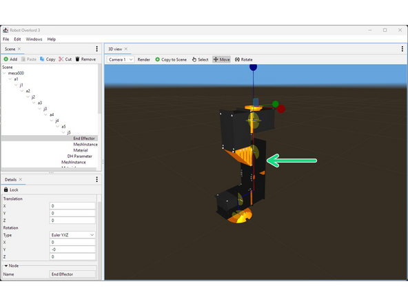
Only do this at the starting position.
-
When you are done it should look like this. Colors should be correct and moving should work correctly.
-
-
-
Insert wisdom here.
-