
-
-
Make sure the robot is designed with the base of the arm at the world origin. The Z axis (blue) should be up. The X axis (red) should be forward.
-
Make sure there is one Component for each moving section of the arm and the base.
-
Hide any internal components. This protects your design secrets and makes the file run smoother.
-
Export each component separately. Remove every component except the one to export, then click on the root of the project, right click, and save as mesh
-
Set the Format to OBJ.
-
Set the Unit Type to centimeters.
-
Export it to a folder on your computer.
-
Use the Undo to restore the deleted components and then repeat for each of the other components.
-
-
-
The easiest way is to modify an existing robot arm. Here we will start by loading the Meca500 example.
-
In the Scene tab, find the first MeshInstance for the base.
-
In the Details tab, click on the Mesh > Load Mesh and choose your OBJ file. You can also select from the list of already loaded meshes.
-
If your model file appears turned the wrong way or the wrong size, you will have to export it again from Fusion360.
-
Repeat for all subsequent MeshInstances.
-
Your mesh files might appear in the wrong position. We will fix them in the next step.
-
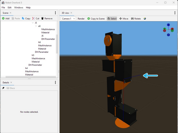
Your arm should look like this. The colors are all wrong but the meshes should be in the right place. We will fix the colors in the next step.
-
-
-
The example file already has some Material settings. These were meant to paint the Meca500 model, not your new design. You will need to change these settings for your arm. Symptoms include incorrect colors or missing parts.
-
In the Scene tab next to each MeshInstance there is a Material node.
-
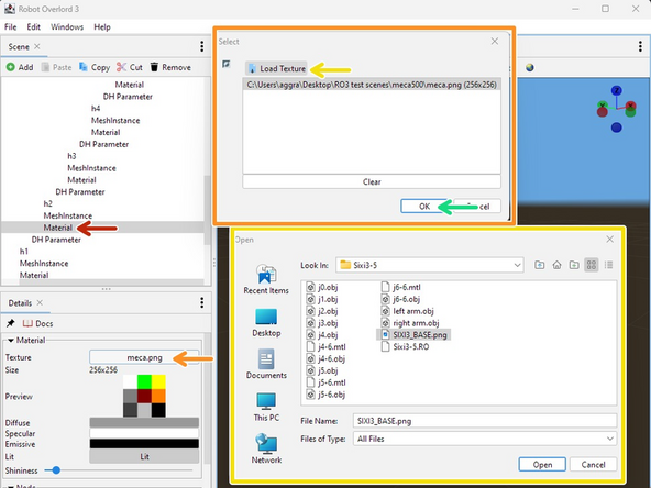
Change the texture. Click the texture button to see the list of loaded textures.
-
If your texture is not already there, click Load Texture and add it.
-
Select your texture and click OK.
-
Your robot should look like this. Notice that the DH parameters are very different from the mesh and moving the arm will look very wrong. We fix that in the next step.
-
Drawing DH parameters and Hinges can be turned on and off in the 3D view tab render menu.
-
-
-
The DH parameters will be wildly different from your new model.
-
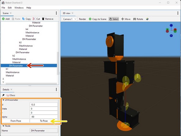
Starting from the first joint, locate the DHParameter node.
-
Adjust the d, theta, r, alpha values to match your new robot arm. You will see the blue and red lines change.
-
The sequence of moves is always translate along z (d), rotate around z (theta), translate along x (r), and rotate around x (alpha). See this video for more information. The DH point of rotation might be somewhere unexpected, even outside the model. It is very possible to design robots that cannot fit in DH parameters, but that's a subject for another day.
-
If you now attempt to move the arm, mesh files will still move incorrectly. With the arm at the default position, Press To Pose to fix them.
-
Only use To Pose in the starting position. The explanation is too long to fit here.
-
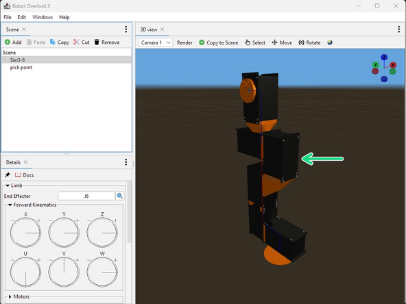
Make sure the End Effector at the last link has the blue line (Z) pointing out of the hand. This way tools will attach correctly.
-
When you are done it should look like this. Colors should be correct and moving should work correctly. Your joint limits will be fixed in the next step.
-
-
-
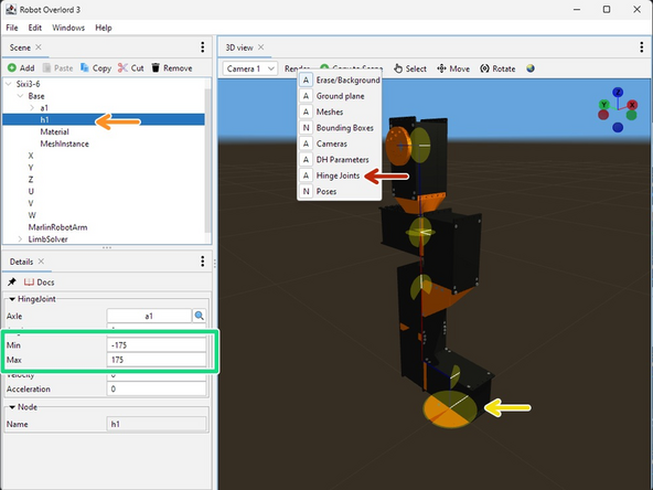
Each rotating part of the robot is a hinge with an axle. The Hinge limits can be seen by setting 3D View > render > hinges to Always.
-
Select a hinge in the Scene tab.
-
Notice the selected hinge becomes larger in the 3D view to make it stand out. The yellow area is the allowed range. The white line is the current position.
-
Adjust the minimum and maximum. If the max is 360 and the min is 0 then the hinge will be unrestricted.
-
Repeat for every hinge in the robot.
-


Congratulations! Your arm should now be moving correctly and following the target. Export it and share it with the world!!
Congratulations! Your arm should now be moving correctly and following the target. Export it and share it with the world!!
