Introduction
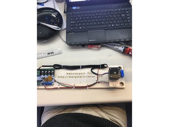
This guide will show all the assembly steps for the Makelangelo 5, which can be purchased - fully assembled and tested - from http://marginallyclever.com/product/make...
Tools
Parts
No parts specified.
-
-
We want this to be easy for everyone. If anything is confusing or could be better, please use the comment button under every step to start a conversation about that step.
-
-
-
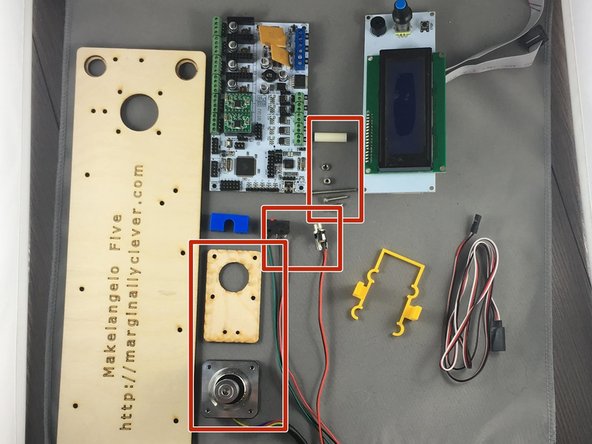
Gather all parts needed for assembly.
-
Gather required tools: socket wrech for M3 nuts, metric alan key for M3 socket head screws, phillips screwdriver, snips, and a soldering iron.
-
Do not start the assembly until you have all the parts and tools required. A half-finished robot is a liability and a heartache.
-
-
-
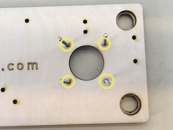
Insert 4 M3 x 10 screws through the indicated holes and thread 4 M3 hexnuts and tighten
-
-
-
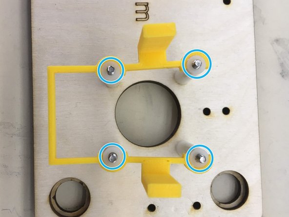
Insert four M3 x 35 screws through indicated holes
-
Slide four 25 mm spacers onto the screws and clip on motor bracket
-
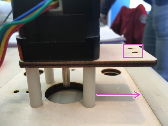
Wood tab with the two holes facing bottom of the board
-
Place motor, lining up screws with the holes, screw in, and unclip the motor bracket.
-
Repeat for left-hand side
-
-
-
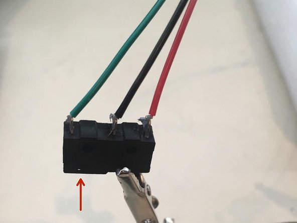
Solder three wires to each switch. From left to right the wire colors should be green, black, red. This assumes the actuator on the switch is also on the left.
-
You will need two switches for each Makelangelo.
-
-
-
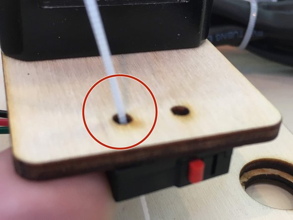
Through one of the two holes put a zip tie through one of the holes on the limit switch
-
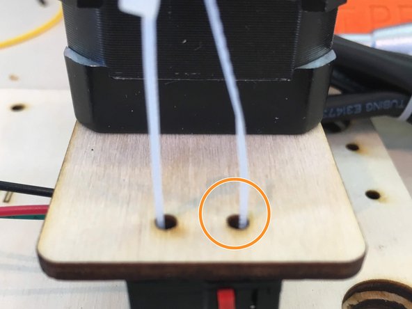
Bend the end of the zip tie around and place back up through the second hole
-
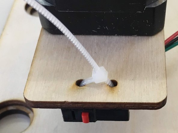
Zip the zip!!
-
-
-
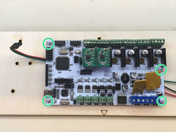
Place wires from right hand limit switch in between the screws for holding the board
-
Put the RUMBA board on the screws and thread and tighten 4 M3 hexnut nylocks onto the four screws poking through
-
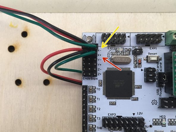
Plug the limit switches into indicated pins. the left switch connects to X- with the green wire on the right.
-
The right switch connects to X+ with the green wire on the right.
-
-
-
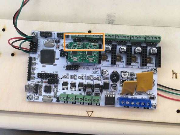
Locate proper pins
-
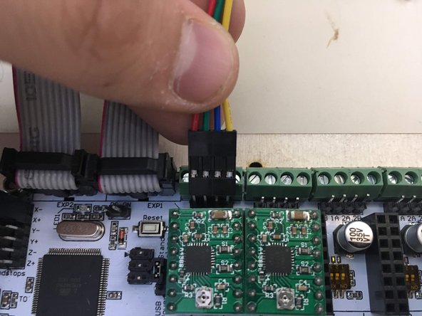
Plug the left motor into the left set of pins and the right motor into the right set
-
Make sure that the yellow wires on both are towards the center
-
-
-
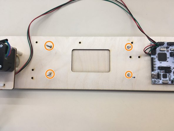
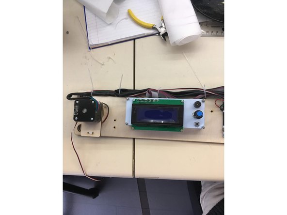
Insert four M3 x 35 screws into the indicated holes
-
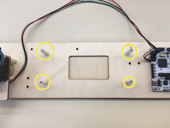
Slide on four 25 mm spacers onto screws
-
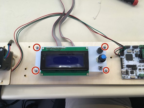
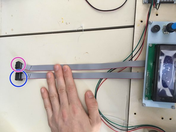
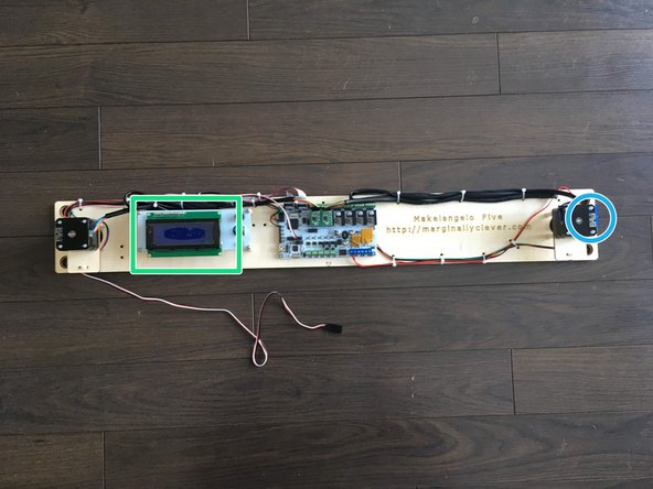
attach the LCD ribbon cables to the LCD panel with both pink lines to the left as shown in picture
-
Place the display onto the screws, with the knob towards the right side, and tighten four M3 hexnut nylocks onto the screws
-
-
-
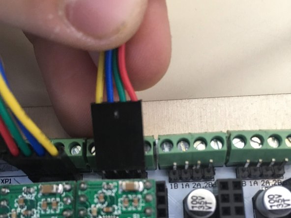
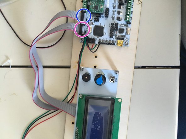
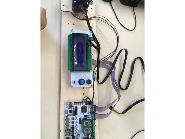
The left most cable coming from the LCD display goes into the right most set of pins, as displayed
-
The right most cable goes into the leftmost set of pins
-
When plugging the plugs onto the board, ensure that the wires are pointing towards the edge of the board
-
-
-
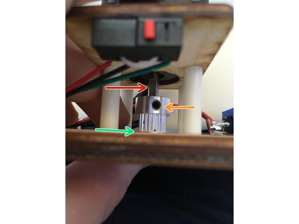
Slide a pully onto motor shafts. Locate the flat side of the motor shaft.
-
Use an alan key to tighten the set screw against the flat side of the motor shaft.
-
The edge of the pulley should be a little above the surface of the wood
-
Repeat for other side.
-
-
-
Take a pair of black and red wires 43 cm in length
-
Solder the black wire to the north pole and the red wire to the west of the power connector following the same techniques used for the switches.
-
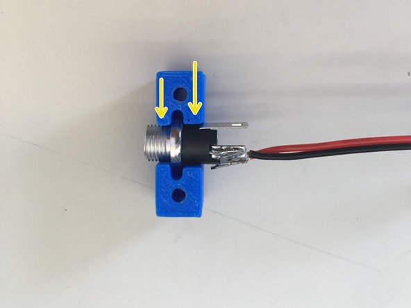
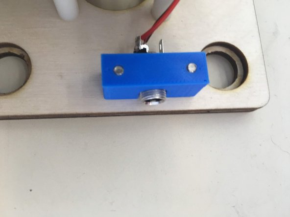
Slide the 12v power plug into holder. Note that once side of the holder is slightly larger than the other. It fits better the correct way around.
-
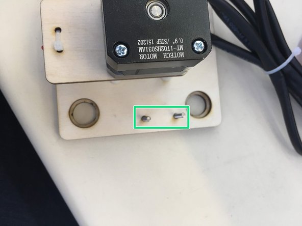
Thread two M3x10 screws into holder through the two extra holes beside the right-hand motor
-
Tighten just enough so that the piece no longer moves! DON'T OVER TIGHTEN!
-
-
-
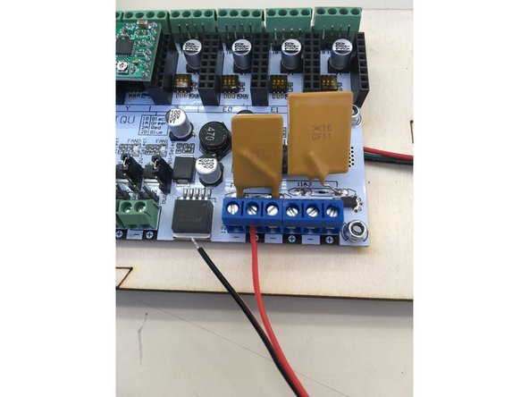
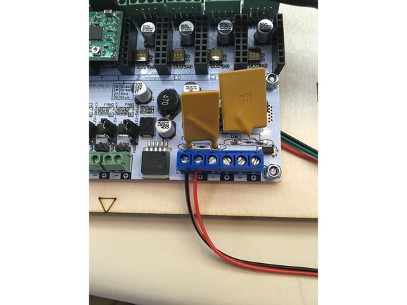
Insert wires from 12v power connector into terminal blocks ensuring that the red wire is inserted into the positive terminal and the black wire is inserted into the negative block
-
-
-
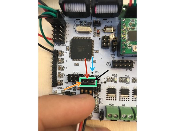
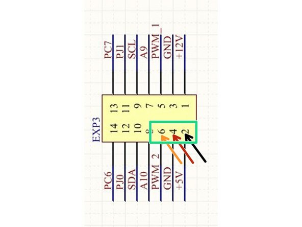
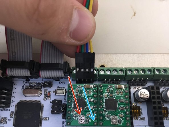
Plug the servo wire onto the board on the bottom row of the EXP3 block.
-
Note the black arrow head pointing to EXP3 pin 1.
-
The black wire lead of the connector goes into EXP3 pin 2.
-
The white wire lead of the connector goes into EXP3 pin 6.
-
That means the middle lead of the connector is in EXP3 pin 4.
-
-
-
Contain all of wires to the board with zip ties using the extra holes spaced all around the board.
-
The goal is to lock down the wires as much as possible so that they cannot catch on anything and get pulled by accident.
-
When you are satisfied with the cable management, cut off the tail end of the zip ties.
-
-
-
plug a 12v2a power supply into the power connector on the right edge of the Makelangelo 5.
-
If the LCD panel does not turn on then probably the grey cables are reversed or plugged in backwards. There are only 4 possible ways to connect them.
-
Using the formula [Vref=8⋅Imax⋅Rcs] find the maximum voltage allowed to keep your stepper motors safe, for example if your motors have 68mΩ of resistance and can allow p to 0.33a then you can find your maximum voltage by rearranging the formula to be: Vref= 8⋅0.33a⋅6.8mΩ. Make sure your Makelangelo meets this by using a multimeter set at 2V.
-
Adjust the dial ONLY with power off. Changing the voltage while connected can destroy the stepper driver.
-
Do this adjustment for both motors. Save time by checking both before disconnecting power. A dial turn of only 10 degrees makes a big difference!
-
-
-
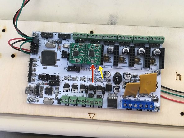
On each motor driver there is a voltage adjustment dial. NEVER turn the dial while power is connected or you will kill the driver.
-
In the bottom right corner is the GND pin.
-
A multimeter can measure the RMS current between these two pins. Ideally the RMS Current = Peak Current x 0.707. For a 0.3a stepper motor the RMS current would be 0.21
-
Measure the RMS current; turn off power; turn the dial 5-10 degrees. Repeat until the RMS current is correct.
-
Test your machine again to ensure smooth moving motors that do not get very hot. (they will still be warm to the touch.)
-