-
-
Package #2
-
Alan Keys
-
Socket Head Driver
-
Plier [Opt.]
-
-
-
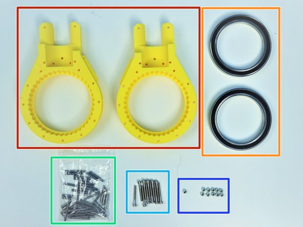
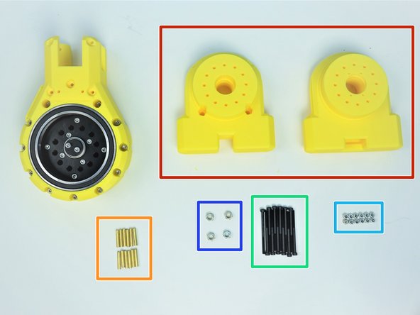
Prepare the following components:
-
[3D] - 2GB Shoulder GB Rotors
-
6702 Bearings [15x21x4mm] (x2)
-
M3x5mm Screws (x16)
-
M3 Hex Nuts (x16)
-
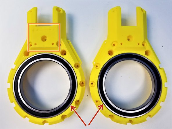
NOTE:
-
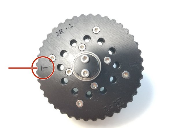
Shoulder Gearbox Rotor consist of 4 similar looking parts, Be aware of T Label and B Label
-
Also Be aware of the Nut Insert vs. Screw Head Insert
-
-
-
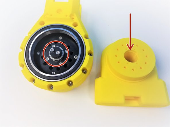
The process for "T" Rotor and "B" Rotor is the same. We will use T rotor as our guide and repeat the same process for B rotor
-
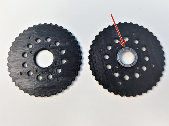
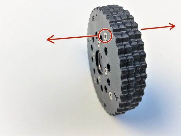
Insert 6702 Bearing on one half of the T Rotor
-
Place the other half and clamp the Bearing together
-
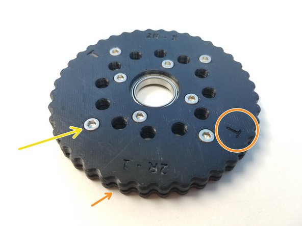
Make sure to align the T label, The holes and the teeth won't line up if this isn't done correctly.
-
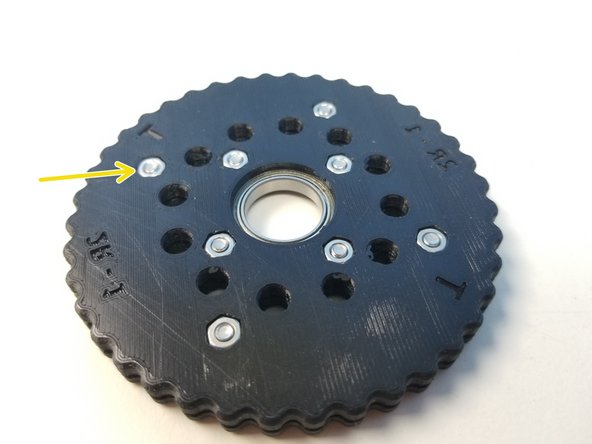
Insert M3x5mm Screws and Hex Nuts on each half of the Rotor and tighten all the Screws.
-
Repeat the same Process for B Rotor
-
-
-
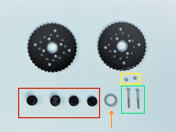
Prepare the following components:
-
Assembled Rotors
-
[3D] - 2GB Eccentric Shafts
-
6702 Bearing [15x21x4mm] (x1)
-
M3 Hex Nuts (x2)
-
M3x30mm Screws (x2)
-
-
-
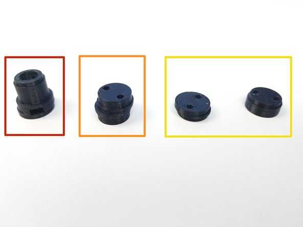
Input Shaft Consist of 4 components:
-
Motor Shaft Coupler
-
Eccentric Cam
-
Shaft Holder Cams (thin piece & thicker concentric piece)
-
Shaft Holder Cams prevent the input shaft to go off on the axis of rotation
-
-
-
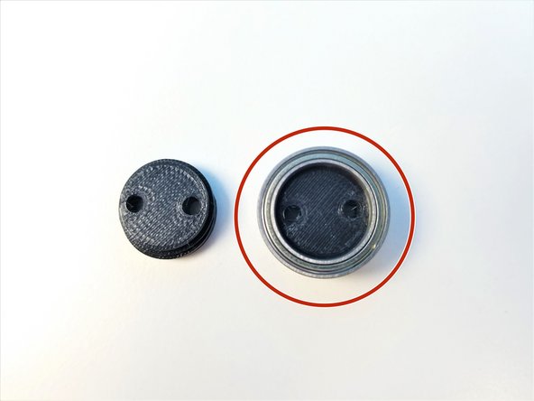
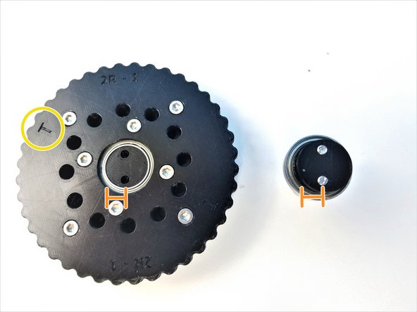
Put the 6702 Bearing on the Thicker Concentric piece of the Shaft Holder
-
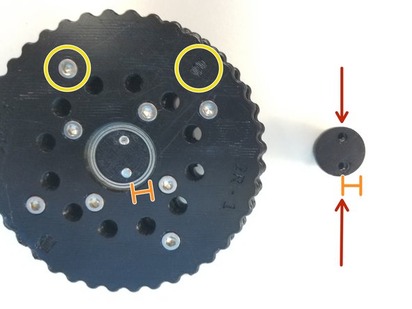
Notice that the thinner piece of the Shaft Holder has 2 sides, one where screw lined up to the center of the face and other which is eccentric
-
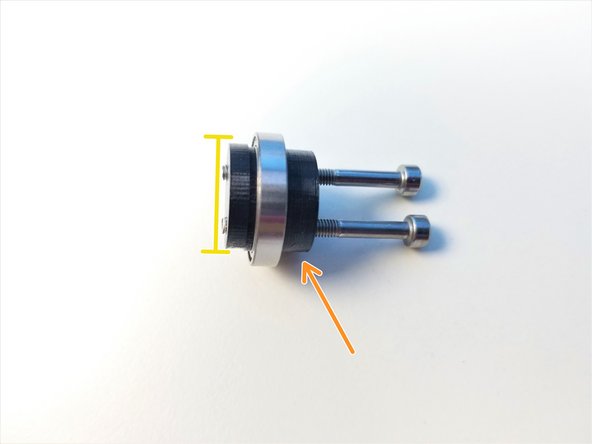
Clamp Shaft Holder Cam pieces using M3x30mm Screws
-
Thicker piece is the Screw Head side,
-
Only screw in until the tip of the screw is flushed with the face of the thinner piece
-
-
-
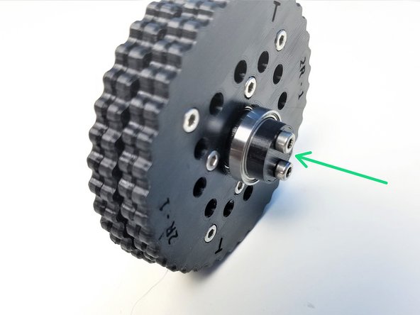
Insert Top & Bottom Rotors on the Eccentric Cam
-
The Screw Head side of each rotor is facing away from each other
-
Align the Eccentric Cam and Shaft Holder Cams and partially screw in the M3x30mm Screws.
-
Check that the T Rotor is facing the Shaft Holder Cam
-
-
-
Insert M3 Hex nuts on the side of the Motor Shaft Coupler
-
Align the Coupler offset and Eccentric Cam offset
-
Make sure the B Rotor and its Screw Head side facing the Coupler
-
Screw in the rest and Tighten it
-
-
-
Prepare the following components:
-
Assembled Input Shaft and Rotors
-
[3D] - 2GB Shoulder GB Housing Top Halves
-
6813 Bearings [65x85x10mm] (x2)
-
Steel dowel pin 91595A130 - [3x24mm] (x41)
-
M3x25mm Screws (x11)
-
M3 Nylock Nuts (x11)
-
-
-
Insert 6813 Bearings on the Housing parts
-
3D-printed housing parts consist of a motor side part and a sensor side part
-
The side with Directional Label is the Motor Side
-
Insert all 41 Steel Pins on the Sensor Side Half of the Housing.
-
-
-
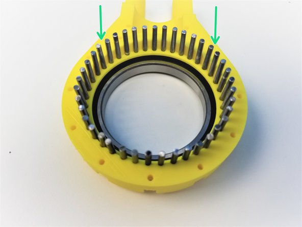
Alignment of the rotor is critical for these gearbox to work.
-
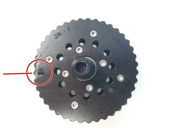
Notice that there are 2 "T" Labels on the T rotor, and same with B rotor with "B" Labels
-
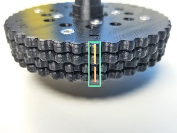
T is aligned in between 2 teeth of the Top Rotor while B is aligned to the middle of a tooth
-
Make a Sharpie Mark in between the teeth of T Rotor Where the "T" is Labeled
-
For B Rotor, Make a sharpie mark on the tooth where the "B" is Labeled.
-
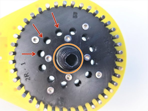
The Correct Alignment will look something like the Third Picture
-
-
-
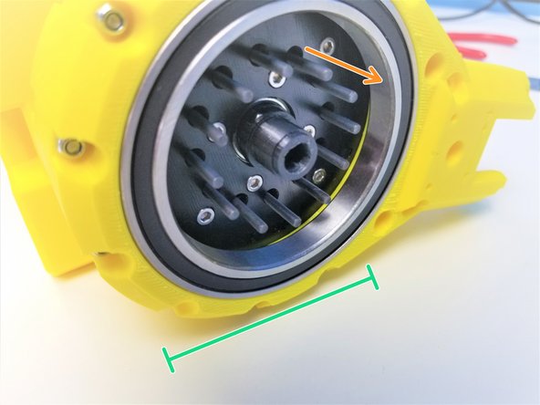
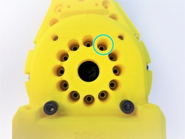
Once the Rotor is Properly aligned, all 12 inner holes will have the same space between them when looking directly above it
-
The Angle of the picture taken of the aligned Rotors are a bit off.
-
Carefully insert the Rotor while maintaining this position on the Housing with the pins.
-
Make sure the Motor Shaft Adapter side of the shaft is Pointing out
-
Clamp the other half of the Housing using M3x25mm Screws and Nylock Nuts
-
Secure tightly using the 5.5mm Socket Driver to hold the Nuts.
-
-
-
Prepare the following components:
-
Assembled Shoulder Gearbox Top
-
[3D] - 2GB Shoulder GB Bottom Halves
-
Brass Tubes [3.5x18.5mm] (x12)
-
M3x45mm Screws (x12)
-
M3 Nylock Nuts (x12)
-
M5 Hex Nuts (x4)
-
-
-
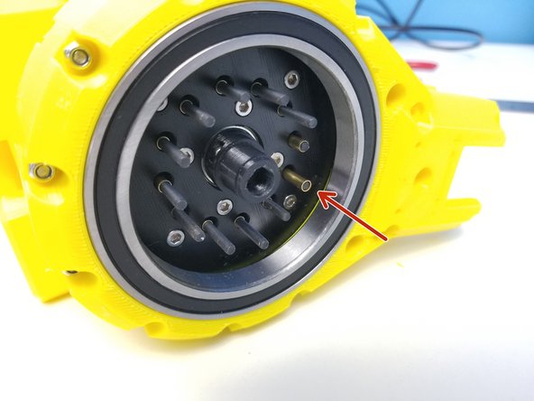
Align the Bearing Insert of the Gearbox Bottom Sensor Side Piece to the Shaft Holder Cam Bearing of the Input Shaft
-
Insert M3x45mm Screws all the way through
-
If Screws aren't going in correctly, you will have to re do the steps, go to aligning the Rotor Step
-
Keep the Gearbox laying on its side for easier assembly
-
-
-
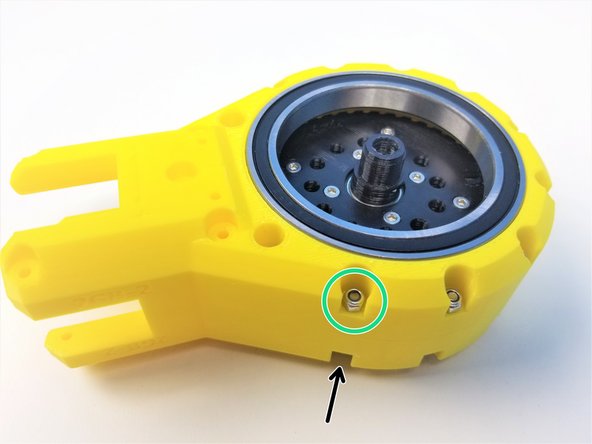
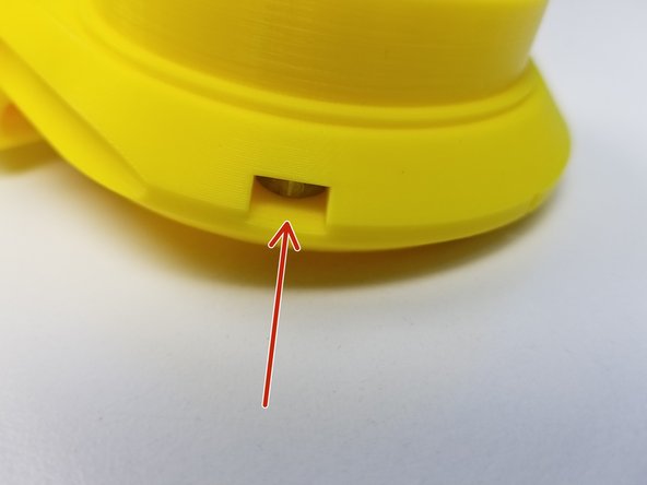
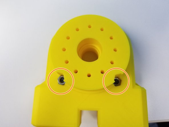
Insert M5 Hex Nuts on the side insert of the Motor Side Bottom Half
-
Insert the other two M5 Hex Nuts on the bottom inserts
-
[Opt.] if the nuts are too loose in the insert, use M5x20mm Screws (or any M5 screws) to hold it in place during assembly
-
-
-
While keeping the Gearbox on its side, insert 3.5x18.5mm Brass Tubes on each Screws
-
Insert the Motor Side of Shoulder Gearbox Bottom and secure it with M3 Nylock Nuts using the Alan Key and Socket Driver
-
-
-
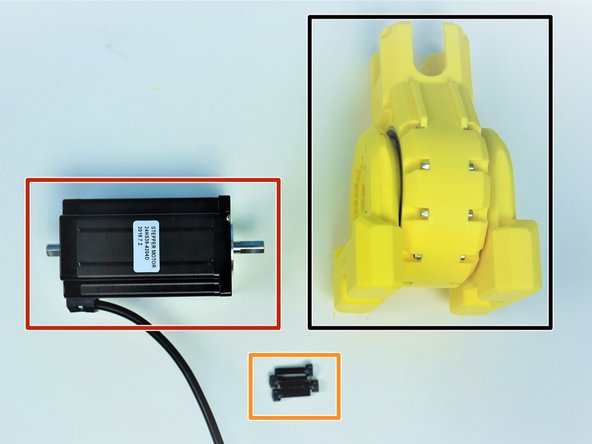
Prepare the following components:
-
Assembled Shoulder Gearbox
-
NEMA24 100mm Motor
-
M5x20mm Screws (x4)
-
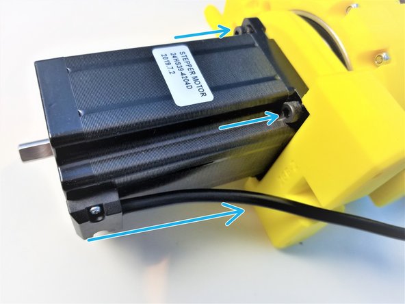
Align the D-Cut of the Motor Shaft to the Gearbox Input Shaft and insert the motor all the way through.
-
Align the motor body so the cable is pointing towards the bottom and secure the position using M5x20mm Screws
-
-
-
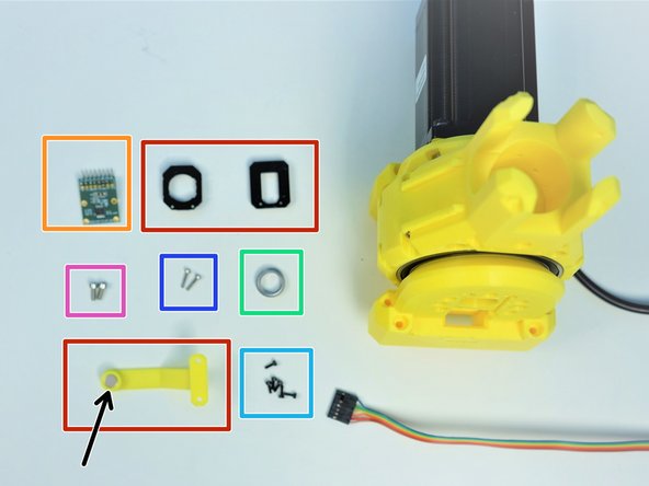
Prepare the following components:
-
[3D] - Sensor Adapter and Magnet Holder Parts
-
AS5147 Sensor [right angle headers on Label Side]
-
8x2.5mm Neodymium Magnet
-
6701 Bearing [12x18x4mm] (x1)
-
M2x6mm Screws (x6)
-
M2x10mm Screws (x2)
-
M3x8mm Screws (x2)
-
-
-
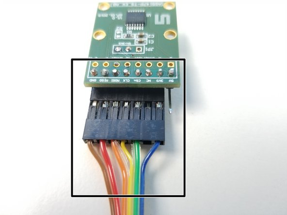
Also prepare 6-pin Ribbon Cable F/O - Brown to Blue {sensor 1 Shoulder} - [365mm]
-
There is a separate assembly guide for all sensor cable which shows the length of each as well.
-
Connect the Cable to the AS5147 Sensor as shown in the second picture
-
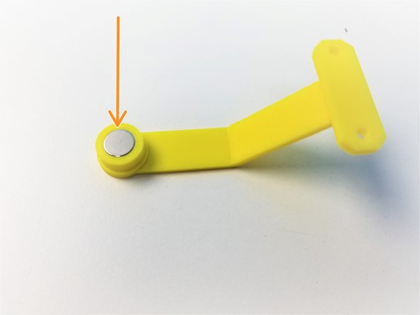
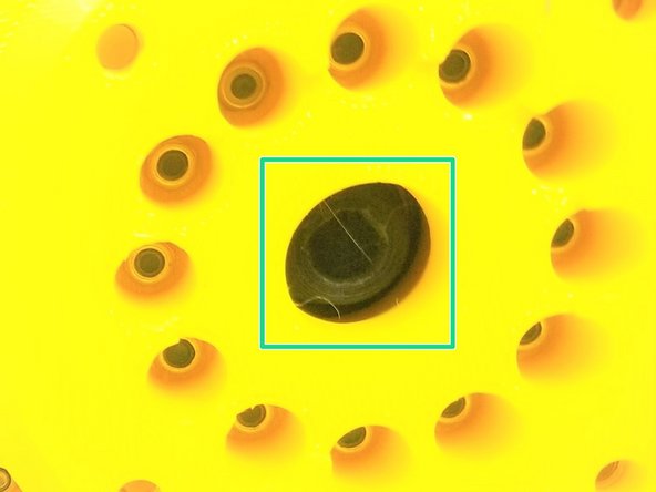
Insert the Neodymium Magnet in the Shoulder Magnet Holder
-
-
-
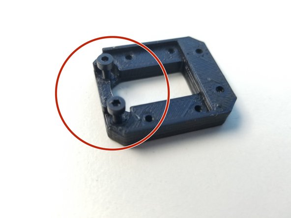
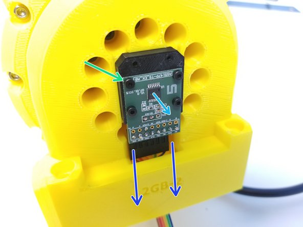
Partially screw in two M2x6mm screws in the Sensor Adapter with the screw head insert.
-
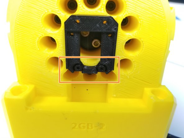
Secure the Sensor Adapter to the Sensor Side of the Gearbox with 2 screw on the bottom side of the 4 holes
-
Feed the Sensor Cable through the Tunnel
-
Then use the remaining M2x6mm Screws to Secure the Sensor to the Sensor Adapter
-
Chip is facing outward
-
-
-
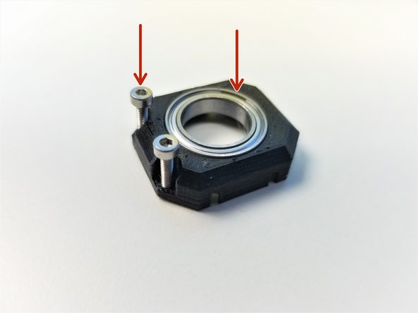
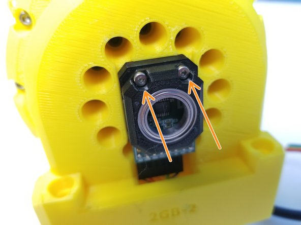
Insert 6702 bearing in the Sensor Bearing Holder part and partially screw in M2x10mm screws
-
Secure the Sensor Bearing Holder to the Sensor Adapter
-
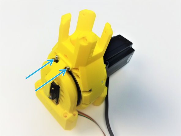
Use M3x8mm Screws to secure the Magnet holder to the Shoulder Gearbox Top
-
-
-
Congratulation! Treat yourself with a candy break.
-


![[3D] - 2GB Shoulder GB Rotors](https://d3t0tbmlie281e.cloudfront.net/igi/mcr/AgEctOPHD6Fl5Y1C.medium)
![[Opt.] if the nuts are too loose in the insert, use M5x20mm Screws (or any M5 screws) to hold it in place during assembly](https://d3t0tbmlie281e.cloudfront.net/igi/mcr/UujeZAdTeITaFNvg.medium)
![Also prepare 6-pin Ribbon Cable F/O - Brown to Blue {sensor 1 Shoulder} - [365mm]](https://d3t0tbmlie281e.cloudfront.net/igi/mcr/PBxpKS6twaEqZbml.medium)