-
-
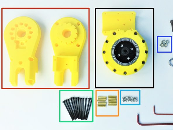
[3D] - Package #3
-
Alan Keys
-
Socket Head Driver - 5.5mm
-
Plier [Opt.]
-
-
-
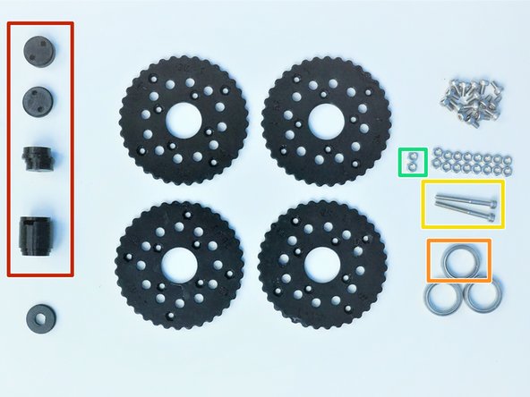
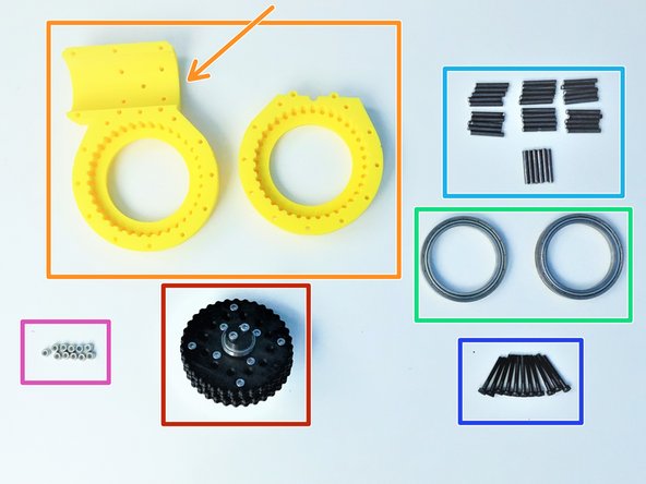
Prepare the following components:
-
[3D] - 3R Elbow GB Rotors
-
6702 Bearings [15x21x4mm] (x2)
-
M3x5mm Screws (x16)
-
M3 Hex Nuts (x16)
-
NOTE:
-
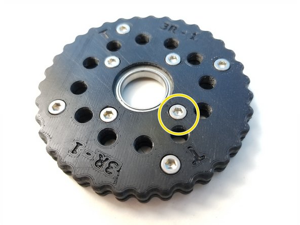
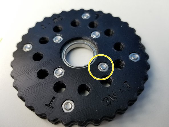
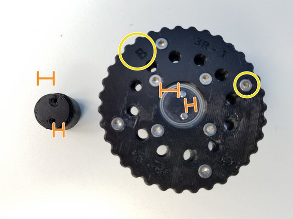
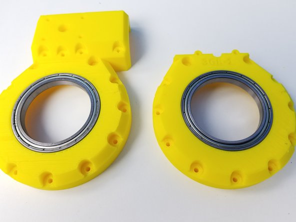
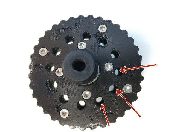
Elbow Gearbox Rotor consist of 4 similar looking parts, Be aware of T Label and B Label
-
Also Be aware of the Nut Insert vs. Screw Head Insert
-
-
-
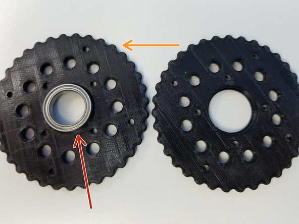
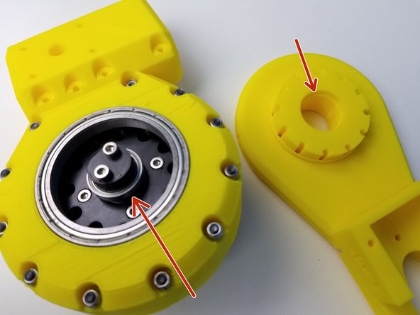
The process for "T" Rotor and "B" Rotor is the same. We will use T rotor as our guide and repeat the same process for B rotor
-
Insert 6702 Bearing on one half of the T Rotor
-
Place the other half and clamp the Bearing together
-
Make sure to align the T labels, The holes and the teeth won't line up if this isn't done correctly.
-
Insert M3x5mm Screws and Hex nuts on each half of the Rotor and tighten all the Screws.
-
Repeat the same Process for B Rotor
-
-
-
Prepare the following components:
-
Assembled Rotors
-
[3D] - 3GB Elbow Eccentric Shaft
-
6702 Bearing [15x21x4mm] (x1)
-
M3x30mm Screws (x2)
-
M3 Hex Nuts (x2)
-
-
-
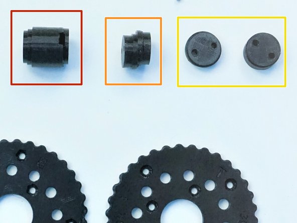
Input Shaft Consist of 4 components:
-
Motor Shaft Coupler
-
Eccentric Cam
-
Shaft Holder Cams
-
For Anti-Twist purposes, these cam holds the bearing. Thinner cam piece holds the Eccentric Cam Bearing in place as well.
-
-
-
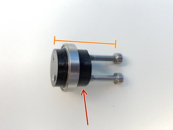
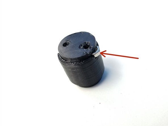
Clamp 6702 Bearing with Shaft Holder Cams using M3x30mm Screws
-
Thicker piece is the Screw Head side,
-
Only screw in until the tip of the screw is flushed with the face of the thinner piece
-
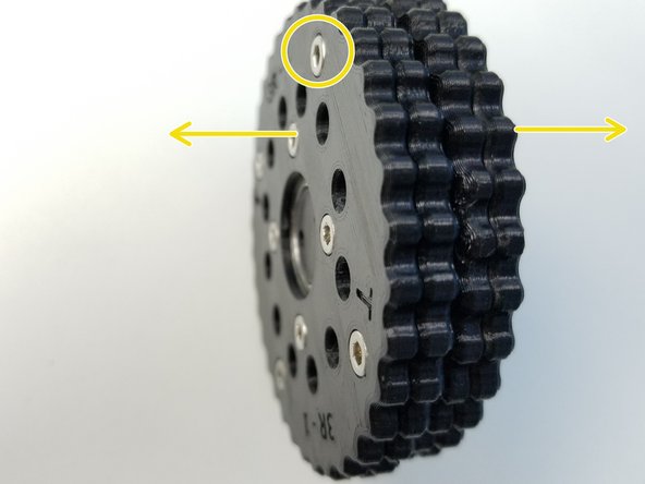
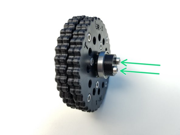
Insert both Rotors on the Eccentric Cam
-
The Screw Head side of each rotor is facing away from each other
-
Align the Eccentric Cam and Shaft Holder Cams and partially screw in the M3x30mm Screws.
-
Check that the T Rotor is facing the Shaft Holder Cam
-
-
-
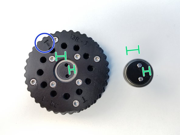
Insert M3 Hex Nuts on the side of the Motor Shaft Coupler
-
Align the Coupler offset and Eccentric Cam offset
-
Make sure the B Rotor and its Screw Head side facing the Coupler
-
Screw in the rest and Tighten it
-
-
-
Prepare the following components:
-
Assembled Input Shaft and Rotors
-
[3D] - 3GB Elbow GB Housing Top Halves
-
NOTE that the one of the Housing Halves has extra extrusion on top, this is the Sensor Side
-
6809 Bearings [45x58x7mm] (x2)
-
Steel dowel pin - [3x24mm] (x36)
-
M3x25mm Screws (x11)
-
M3 Nylock Nuts (x11)
-
-
-
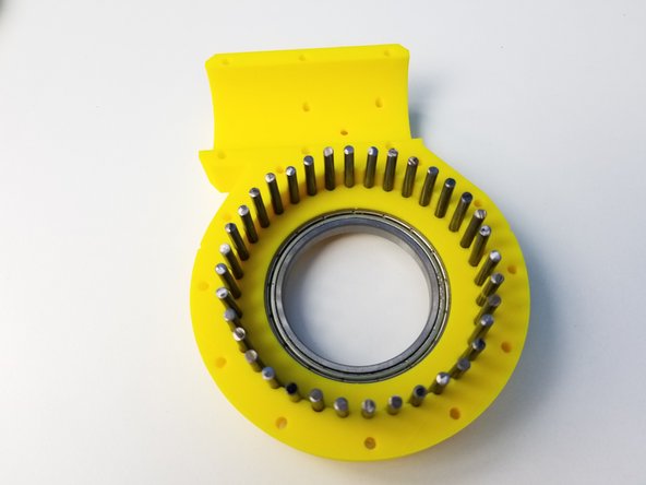
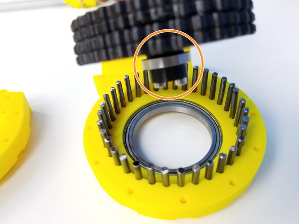
Insert 6809 Bearings on the Housings
-
Insert all 36 Steel Pins on the Sensor Side Half of the Housing
-
-
-
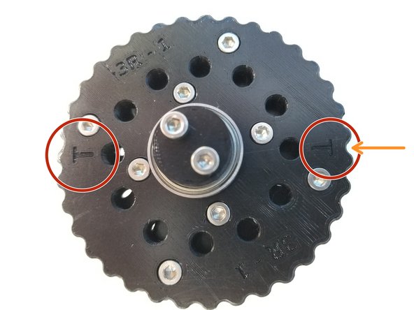
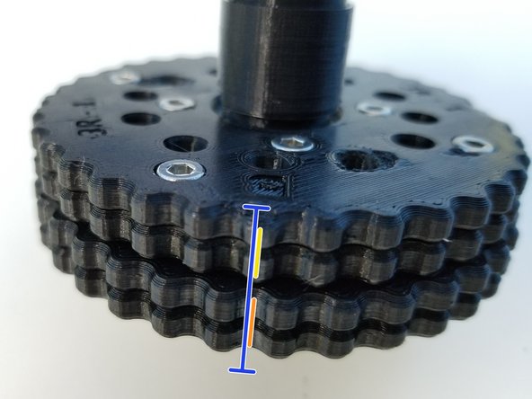
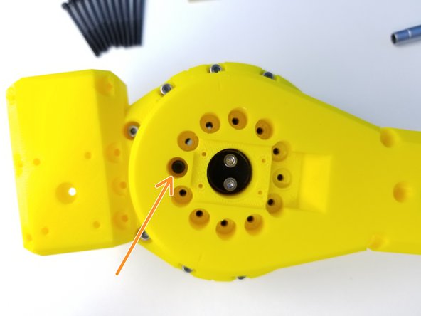
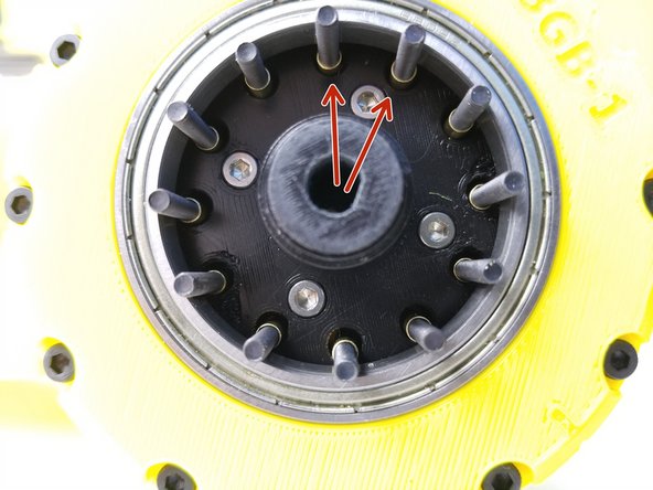
Alignment of the rotor is critical for these gearbox to work.
-
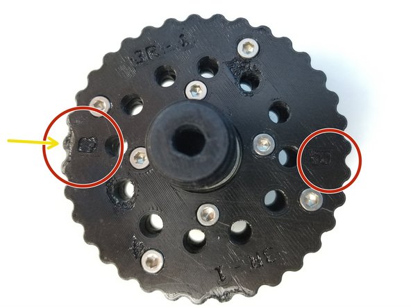
Notice that there are 2 "T" Labels on the T rotor, and same with B rotor with "B" Labels
-
One "T" is on the Tooth and the other "T" is in between 2 Teeth, This is also the same with B rotor
-
Make a Sharpie Mark in between the teeth of "T" Rotor Where the "T" is Labeled
-
For B Rotor, Make a sharpie mark on the tooth where the "B" is Labeled.
-
The Correct Alignment will look something like the Third Picture
-
-
-
Once the Rotor is Properly aligned, all 12 inner holes will have the same space between them when looking directly above it
-
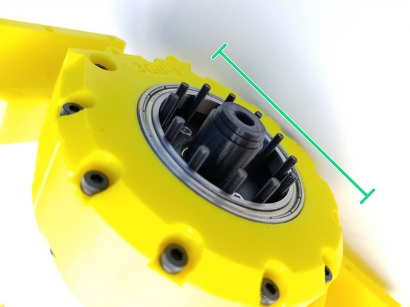
Carefully insert the Rotor while maintaining this position on the Housing with the pins.
-
Make sure the Shaft Holder Cam side of the shaft is going in first
-
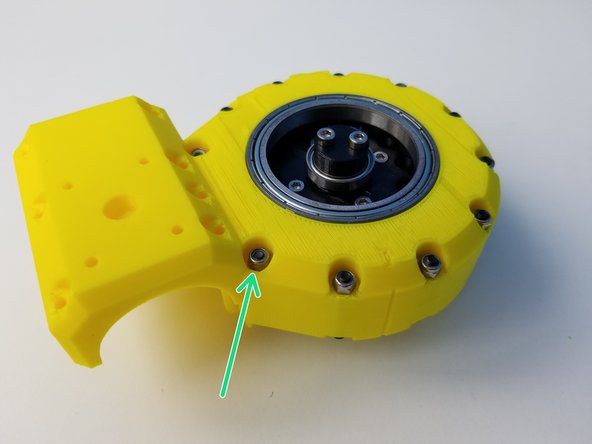
Clamp the other half of the Housing using M3x25mm Screws and Nylock Nuts
-
Secure tightly using the 5.5mm Socket Driver to hold the Nuts.
-
-
-
Prepare the following components:
-
Assembled Elbow Gearbox Top
-
[3D] - 3GB Elbow GB Bottom Halves
-
Brass Tubes [3.5mmx18.5mm] (x12)
-
M3x45mm Screws (x12)
-
M3 Nylock Nuts (x12)
-
M5 Hex Nuts (x4)
-
-
-
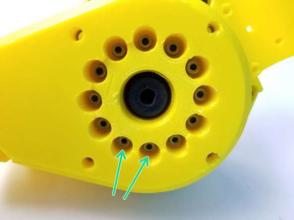
Align the Bearing Insert of the Gearbox Bottom Sensor Side Piece to the Shaft Holder Cam Bearing of the Input Shaft
-
Insert M3x45mm Screws all the way through
-
If Screws aren't going in correctly, you will have to re do the steps, go to aligning the Rotor Step
-
Keep the Gearbox laying on its side for easier assembly
-
-
-
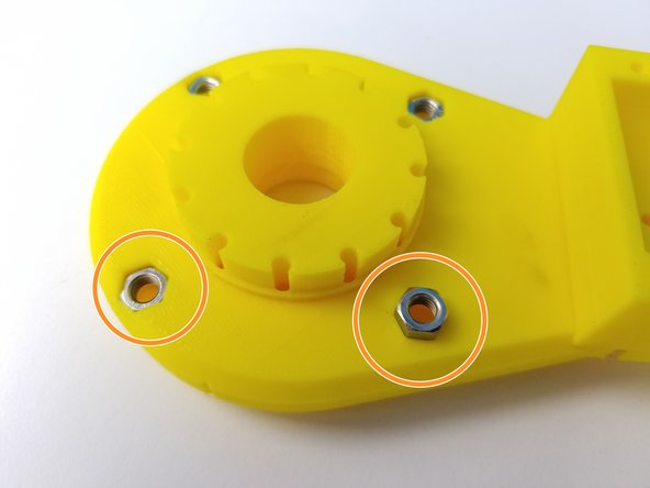
While keeping the Gearbox on its side, insert 3.5x18.5mm Brass Tubes on each Screws
-
Insert M5 Hex Nuts on the Motor Side of the Elbow Gearbox Bottom
-
Insert the other Half of the Elbow Gearbox Bottom and secure it with M3 Nylock Nuts using the Alan Key and Socket Driver
-
-
-
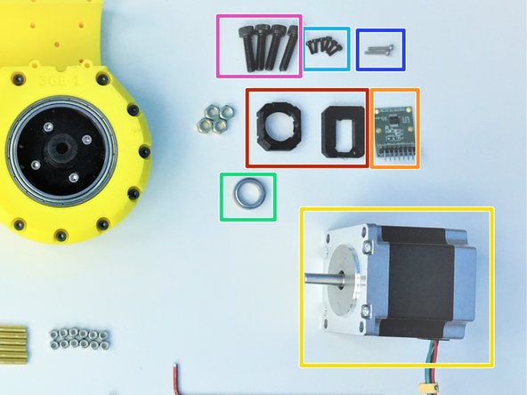
Prepare the following components:
-
[3D] - Sensor Adapter Parts
-
AS5147 Sensor [right angle headers on chip side]
-
NEMA23 56mm Motor
-
6701 Bearing [12x18x4mm] (x1)
-
M2x6mm Screws (x6)
-
M2x10mm Screws (x2)
-
M5x20mm Screws (x4)
-
-
-
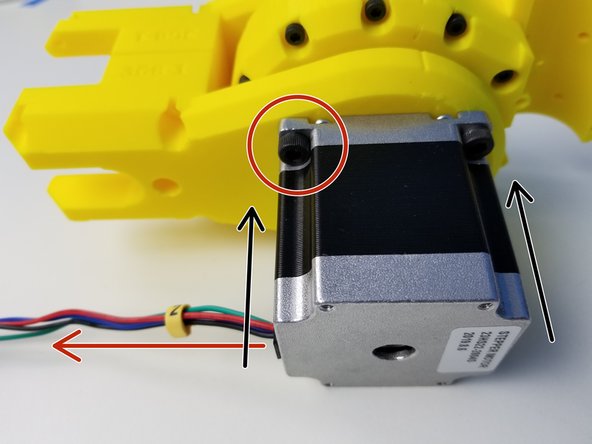
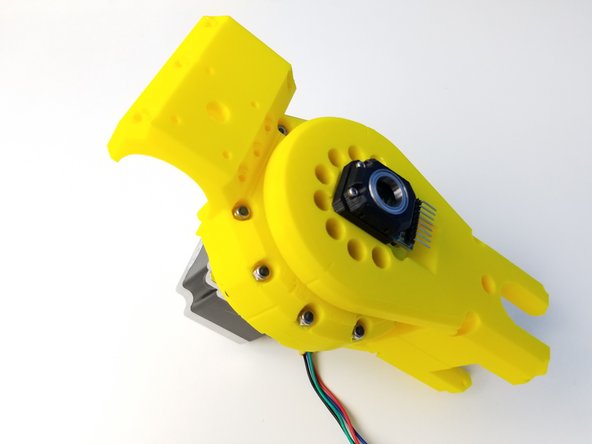
Align the D-Cut of the Motor Shaft to the Gearbox Input Shaft and insert the motor all the way through.
-
Rotate the motor body so the cable is pointing towards the bottom and secure the position using M5x20mm Screws
-
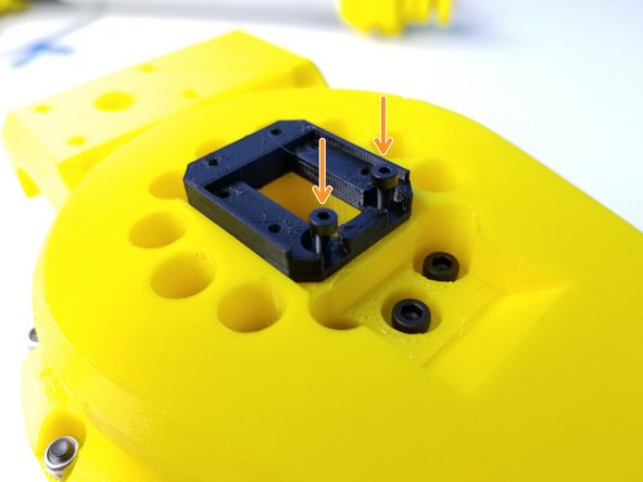
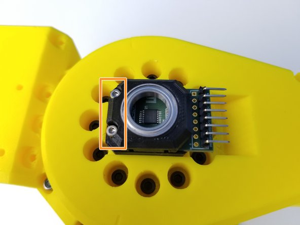
Secure the Sensor Holder using M2x6mm Screws
-
Notice the position of the Sensor holder
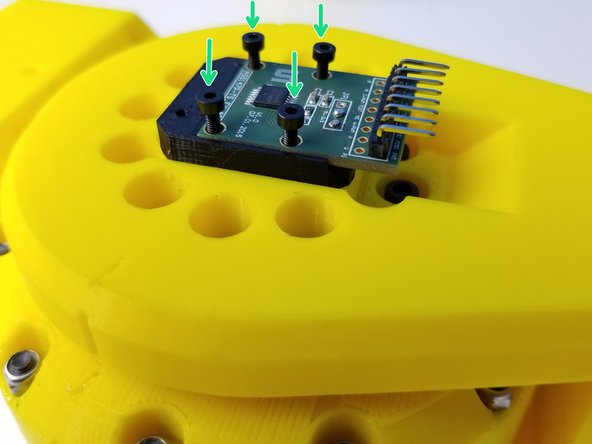
-
Then use the remaining M2x6mm Screws to secure the AS5147 Sensor.
-
-
-
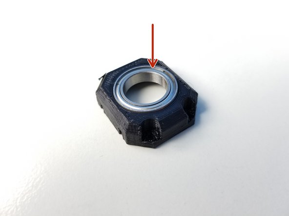
Insert 6702 Bearing in the Sensor Bearing Holder
-
Secure the Sensor Bearing Holder part using M2x10mm screws
-
-
-
Congratulation, give yourself a high five! or the closest living thing near you!
-
![[3D] - Package #3](https://d3t0tbmlie281e.cloudfront.net/igi/mcr/4ukeBEpy3HuIiaDh.medium)

![[3D] - 3R Elbow GB Rotors](https://d3t0tbmlie281e.cloudfront.net/igi/mcr/ygZtmqflamvDRNMi.medium)