-
-
Assembled Picasso Box
-
Assembly Ulna Gearbox & Elbow Tail
-
[3D] - 6E Picasso Wrist Gearbox Components
-
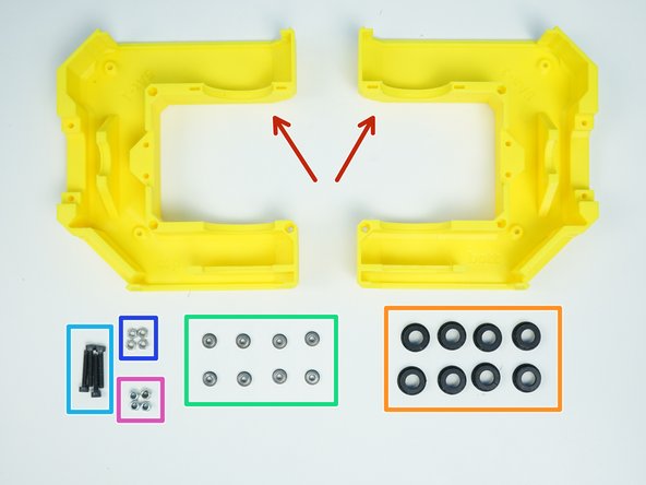
[3D] - 5A Fork Components
-
Alan Keys
-
Socket Head Driver
-
Plier [Opt.]
-
-
-
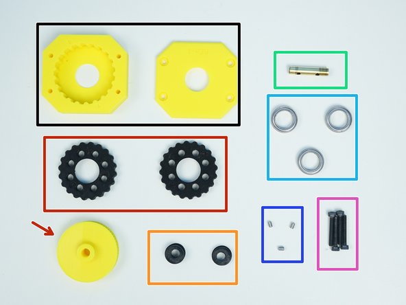
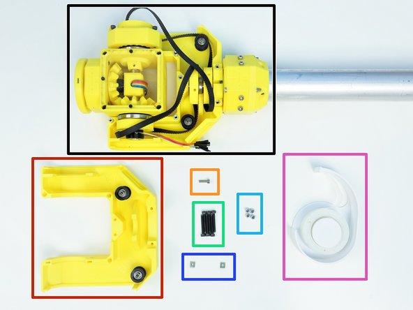
Prepare the following components:
-
Assembled Picasso Box
-
[3D] - 6Ea Picasso GB Output Disks
-
6706 Bearing [30x37x4mm] (x1)
-
M3x10mm Screws (x4)
-
M3x20mm Screws (x8)
-
M3 Hex Nuts (x8)
-
-
-
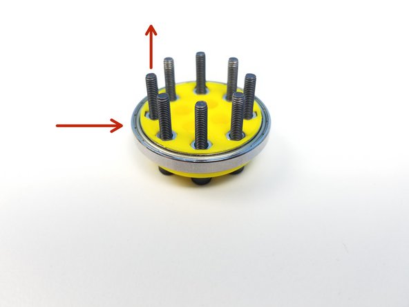
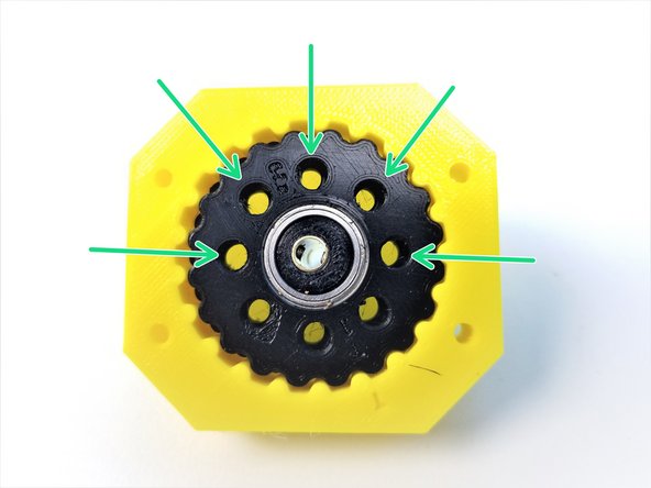
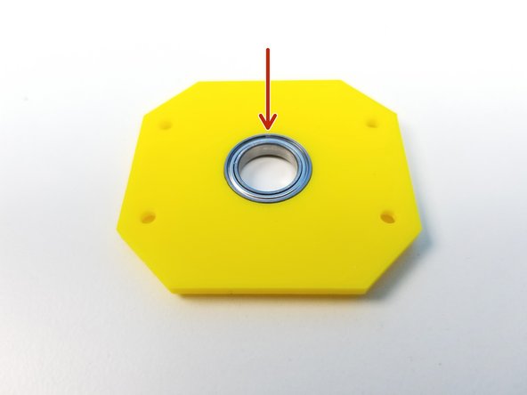
Clamp 6706 Bearings with two Output Disk components using M3x20mm screws and Hex Nuts
-
Tighten these nuts as well
-
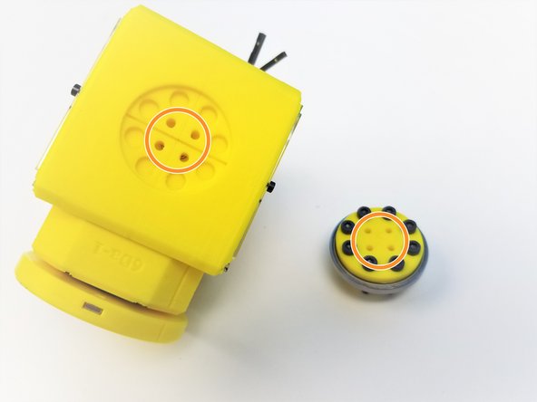
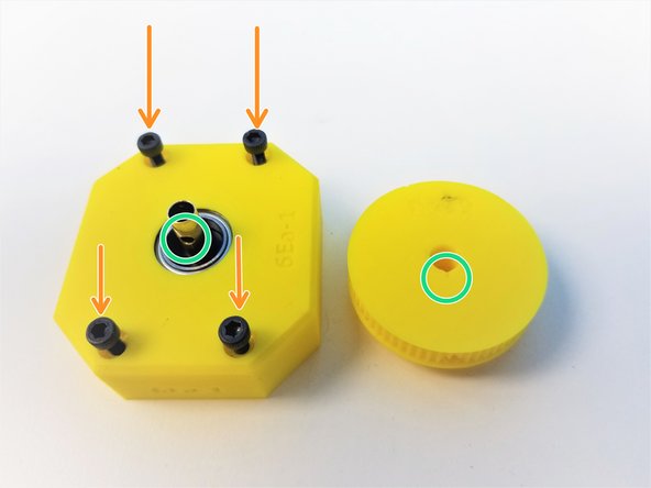
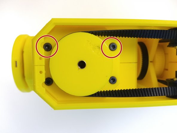
Align the 4 Middle Holes of Clamped Output Disk to the side of the Picasso Box
-
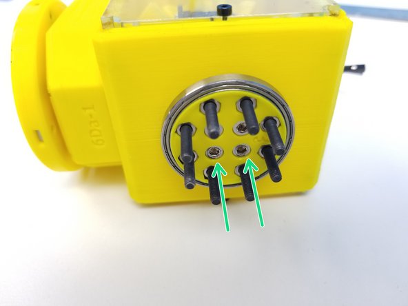
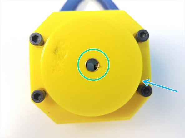
Secure the clamped output disk to the side of the Assembled Picasso Box using M3x10mm Screws
-
-
-
Prepare the following components:
-
[3D] - 6Ea Picasso GB Housing
-
[3D] - 6Ea Picasso GB Rotors & 6PE Pulley Gear
-
[3D] - 6Ea Picasso GB Eccentric Cams
-
Brass Tube [7/32' x 25.95mm]
-
6701 Bearings [12x18x4mm] (x3)
-
M3x4mm Set Screws (x3)
-
M3x20mm Screws (x4)
-
-
-
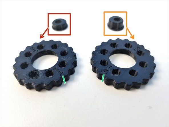
Eccentric Cams
-
"Thin/Top" Eccentric Cam
-
"Thick/Bottom" Eccentric Cam
-
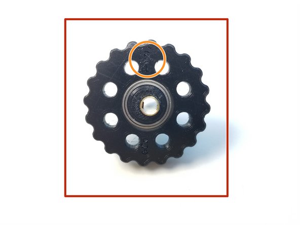
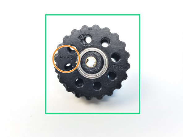
Rotors
-
Make a sharpie mark on the side of the Rotor where it lines up with the B and T label on each Rotors
-
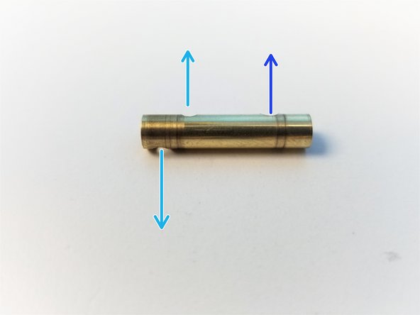
Brass Tube
-
Tube end with the two drilled holes = Cam End
-
Tube end with the one drilled hole = Pulley End
-
-
-
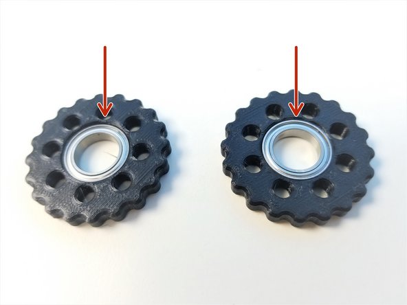
Insert 6701 Bearings to both Top and Bottom Rotors as well as the Top Housing
-
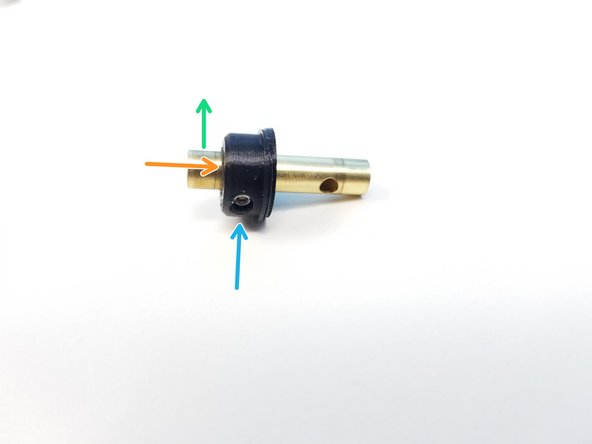
Slide the Bottom Eccentric Cam to the 2nd hole from the edge in the Cam End of the Brass Tube
-
First hole is on the other side of the Tube
-
Align the set screw holes and screw its place using the M3x4mm Set Screw
-
-
-
Slide the Bottom Rotor to the Bottom Eccentric Cam
-
Label Side of the Rotor is facing the Cam End
-
Repeat the process with the Top Eccentric Cam and Rotor
-
Label Side of the Rotor is facing the Cam End
-
-
-
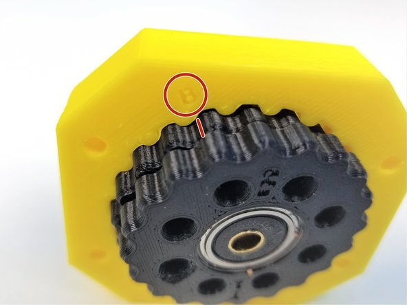
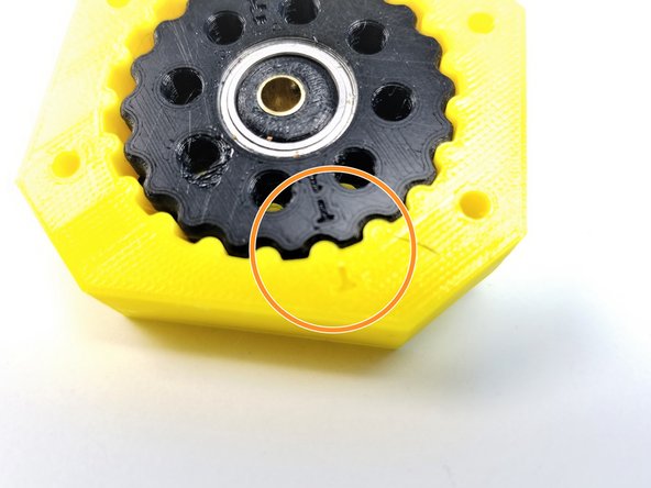
Align the Side Sharpie mark on the Bottom Rotor to the "B" label on the Housing and slide only the Bottom Rotor into the Housing
-
Align the Side Sharpie mark on the Top Rotor to the "T" labelled on the Housing and slide the rest of the Rotor in.
-
If everything went smoothly, the gap between 8 holes on each rotor should be equally spaced
-
-
-
Insert 6701 Bearing on the Top Housing
-
Secure the Top Housing to the Rotor Housing using the M3x20mm Screws
-
DON't screw all the way in. Just to the flushed to the bottom of the Main Housing
-
Align the Pulley Gear to the Set Screw and slide in the Pulley gear to the Brass Tube
-
Secure it using M3x4mm Set Screw
-
-
-
Prepare the following components:
-
[3D] - 5Aa Fork {Bottom & Top}
-
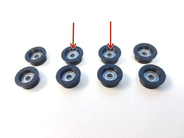
[3D] - 5I Idler Bearing Cover (x8)
-
MF83 Flanged Bearings [3x8x4mm] (x8)
-
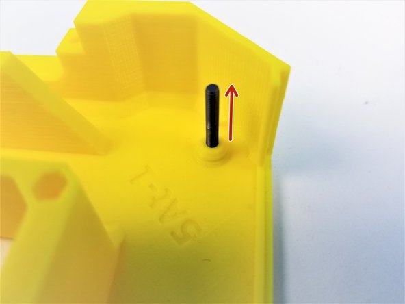
M3x20mm Screws (x4)
-
M3 Hex Nuts (x4)
-
M3 Nylock Nuts (x4)
-
-
-
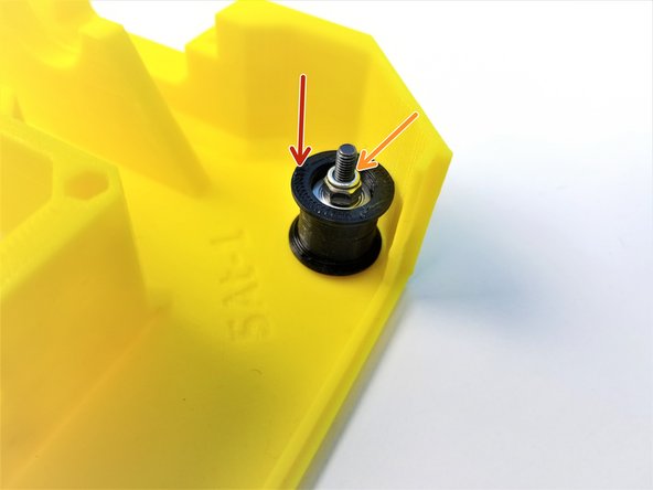
Insert MF83 Bearings into the Bearing Sleeves
-
Insert the M3x20mm Screw in to the Fork Half where there's a chamfered peg on the inner face
-
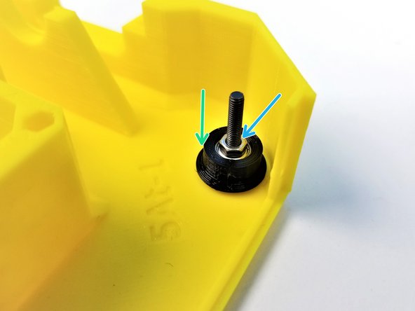
Slide one of the Bearing Sleeves to the M3x20mm Screwss with the flanged part on the bottom
-
Use M3 Hex Nut to secure the Bearing Sleeve in place
-
-
-
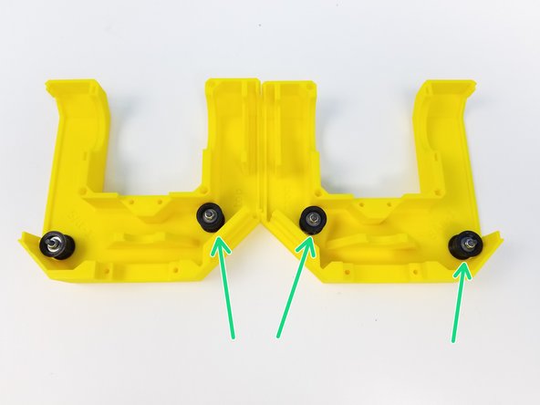
Insert another one of the Bearing Sleeves on the M3x20mm Screws but this time with the flanged part facing up
-
Use M3 Nylock Nuts to secure it in place
-
Repeat the procedure for 3 other locations.
-
-
-
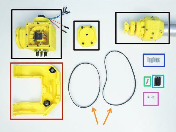
Prepare the following components:
-
Assembled Ulna Gearbox, Picasso Box and Wrist Gearbox
-
Fork Bottom {w/ Idler installed}
-
Timing Belt GT2-336mm & GT2-400mm
-
M3x10mm Screw (x1)
-
M3x22mm Screws (x6)
-
M3x4.5x12mm Hex Standoffs (x7)
-
M3 Square Nuts (x2)
-
-
-
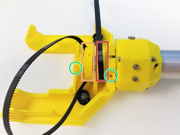
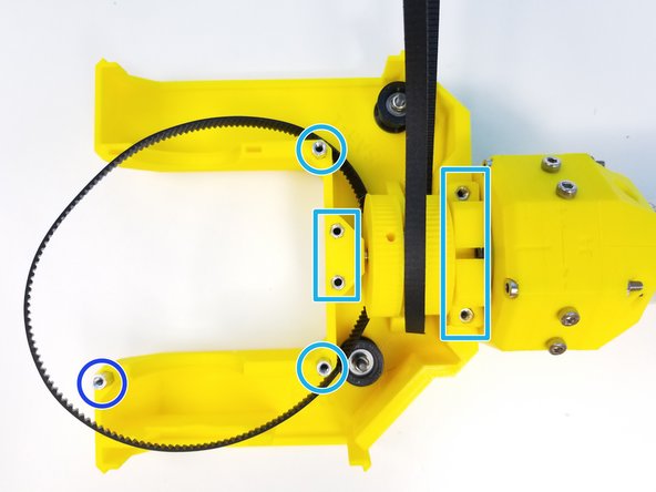
Place the GT2x400mm Timing Belt on the outer pulley on Assembled Ulna Gearbox
-
Place the GT2x336mm Timing Belt on the inner pulley
-
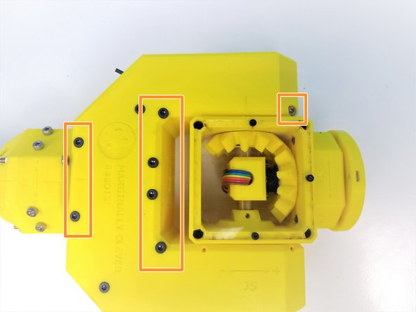
Align the Ulna Sensor Plate and Ulna Output Gearbox to the Fork Bottom with the Hex Standoff insert pointing upward
-
Insert M3x4.5x12mm Hex standoffs and secure its place using M3x22mm Screws
-
Use M3x10mm Screw in this location
-
-
-
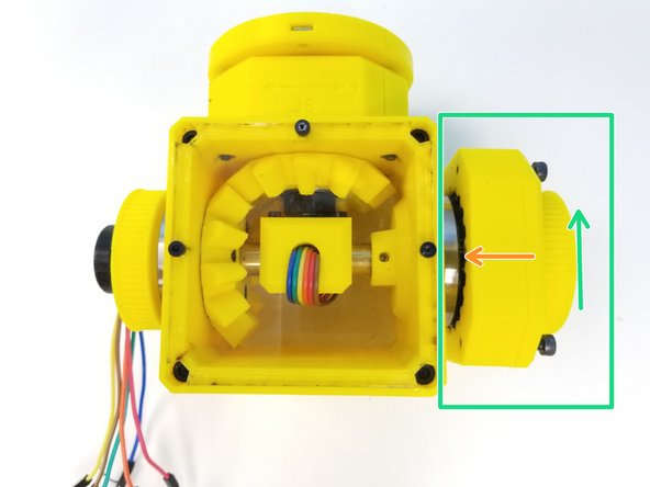
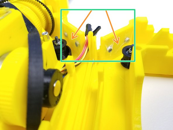
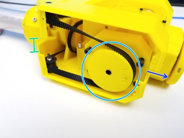
Insert the Picasso Output pins to the Picasso Gearbox
-
Rotate the Input Pulley of the Picasso Gearbox to align the gearbox housing
-
Insert the assembled Picasso Box into the Bearing Slots of the Fork Bottom
-
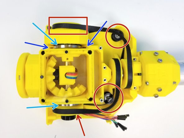
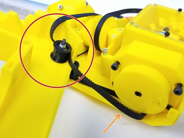
Make sure to wrap the Timing Belts on both Pulley Gears AND the Bottom Idlers
-
The SMOOTH SIDE of the Belt on the IDLERS
-
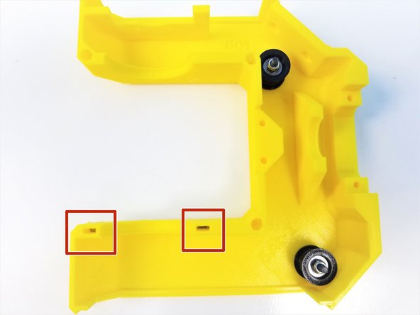
Insert M3 Square Nuts in the Square Nut insert on the Fork Bottom
-
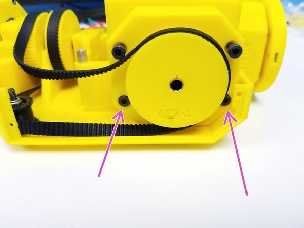
Secure the Picasso Gearbox by tightening the bottom screws on the Gearbox Housing
-
-
-
Prepare the following components:
-
Fork Bottom Prepared
-
Fork Top {w/ Idlers Installed}
-
M3x10mm Screw (x1)
-
M3x25mm Screws (x6)
-
M3 Nylock Nuts (x4)
-
M3 Square Nuts (x2)
-
[Opt.] - Tape
-
-
-
Insert the M3 Square Nuts in the Fork Top
-
Insert the M3 Nylock Nuts in both Fork Top and Bottom on the side wall
-
Optionally, put tape over the nuts as the friction fit alone may not be enough to keep them on.
-
-
-
This step may be the hardest to execute so follow through carefully. Use Alan Key as a "hook" if you need to
-
Align the 400mm GT2-Timing Belt {outer belt} to the Top Idler
-
Take the Belt off of the Gearbox Pulley if you need to.
-
Make sure the SMOOTH side of the belt is on the Idler
-
Rotate the Top Fork and let it FLOAT over the Bottom Fork
-
Put the 400mm Belt back on the Pulley
-
Notice that the Top Fork is shifted forward relative to the Bottom Fork
-
While the Fork is shifted forward, put the 336mm GT2-Timing Belt on the Inner Pulley on the other side
-
-
-
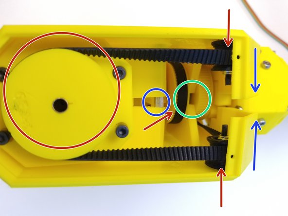
Make sure the both Inner and Outer Belts are on ALL the Pulley Gears
-
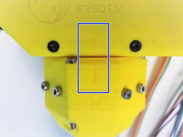
Shift the Top Fork back and align the "Pulley Separating Wall"
-
Double check that the Picasso Gearbox Side is all good too
-
Once all Hex Standoffs are aligned too, Clamp the Top Fork down
-
-
-
Secure the Picasso Gearbox to the Top Fork by tightening the top screws on the Housing
-
Use M3x25mm Screws and M3x10mm screw to secure the Top Fork to the Bottom Fork
-
-
-
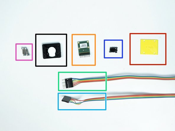
Prepare the following components:
-
[3D] - Sensor Adapter 2
-
[3D] - Fork Cable Clamp Plate
-
AS5147 Sensor {right angle header on the label side}
-
Hand Sensor Cable Extension {numbered 5w/ male connector}
-
Wrist Sensor Cable {numbered 4}
-
M2x6mm Screws (x8)
-
M3x10mm Screws (x4)
-
-
-
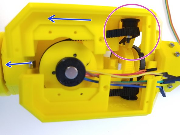
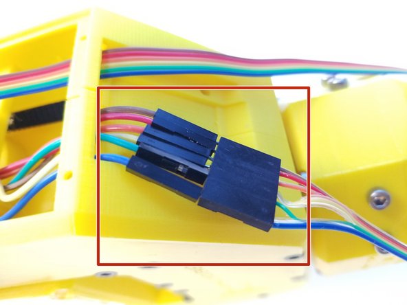
Connect the Hand Sensor Cable Extension to the Wires that comes out of the Picasso Box {Hand Sensor}
-
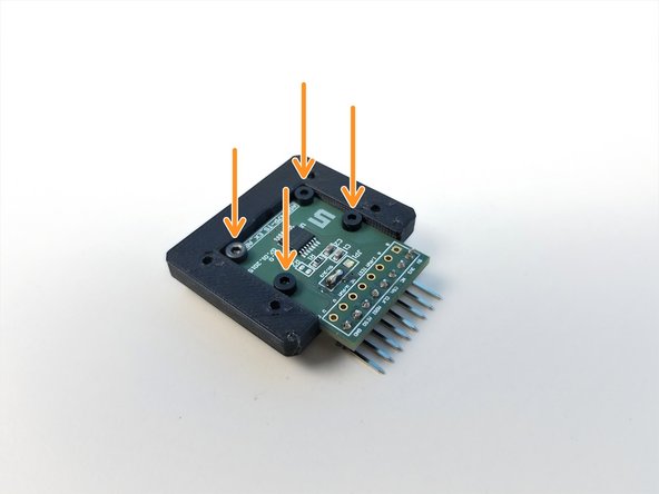
Mount AS5147 Sensor to the Sensor Adapter 2 using M2x6mm Screws
-
Insert the Wrist Sensor Cable {Female} through the Cable Clamp
-
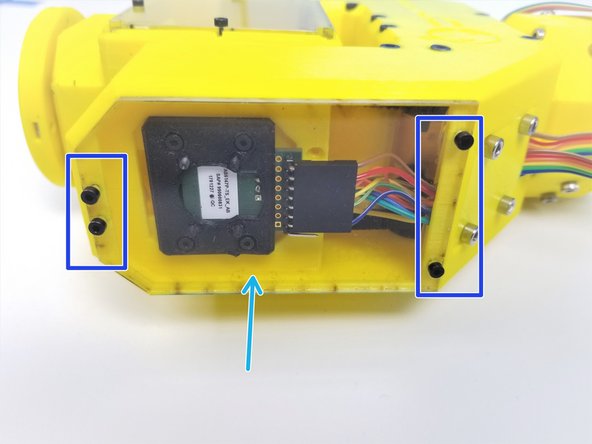
Connect the Wrist Sensor Cable to AS5147 Sensor
-
If you don't remember the Connection Orientation from previous steps, just copy the picture.
-
-
-
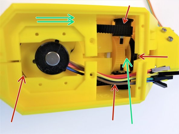
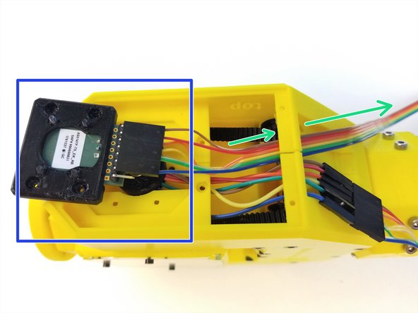
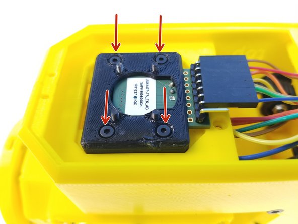
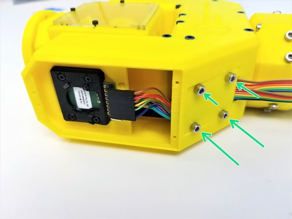
Use M2x6mm Screws to secure the Sensor Adapter to the Fork
-
Organize the Cables on the Cable Clamp area
-
The Hand Sensor Connector is below the Wrist Sensor Cable
-
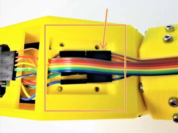
Use M3x10mm Screws to clamp the sensor cables with Fork Cable Clamp Plate
-
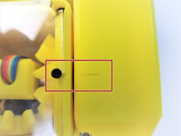
There's only one orientation that the Clamp Plate can go on,
-
Make sure the Version Label is facing the Cable
-
Chamfered Part is where the Cable comes Out
-
-
-
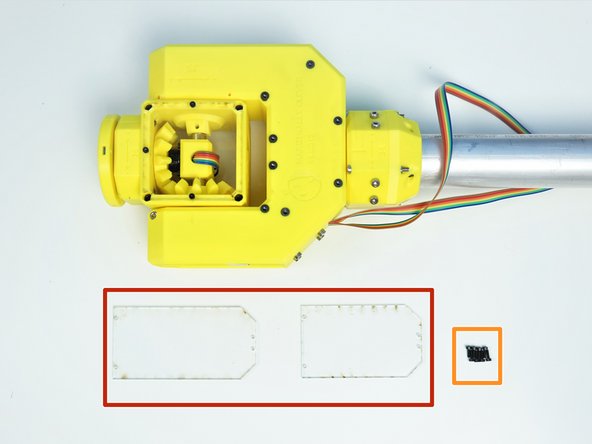
Prepare the following components:
-
[LSR] - Fork Acrylic Plates {Large & Small}
-
M2x6mm Screws (x8)
-
Small Acrylic Plate goes on the Sensor Side
-
Large one goes on the Wrist Gearbox Side
-
Secure them with M2x6mm Screws
-
-
-
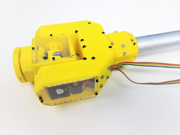
Rotate the Motor Shafts on the Elbow Tail Side to rotate the joints
-
Align the Picasso Box to the Fork
-
Align the Fork to the Ulna Gearbox
-
-
-
Congratulation! You are nearly there!!!
-


![[LSR] - Fork Acrylic Plates {Large & Small}](https://d3t0tbmlie281e.cloudfront.net/igi/mcr/3BYQU4p6n3x2opJu.medium)