-
-
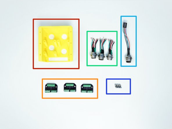
[3D] - Anchor Components
-
[LSR] - Anchor Base Plate
-
Cable Management Components
-
Alan Keys
-
Pliers
-
-
-
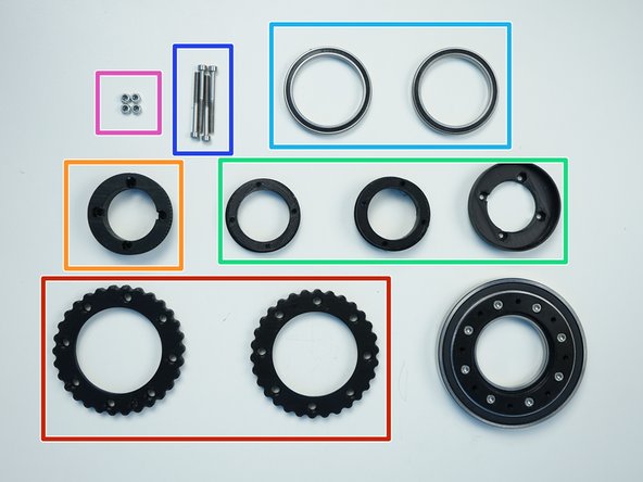
Prepare the following components:
-
[3D] - 1GB Output Disks Bottom {screw head side & nut insert side}
-
6708 Bearings [40x50x6mm] (x1)
-
6813 Bearing [65x85x10mm] (x1)
-
M3x10mm Screws (x8)
-
M3 Nylock Nuts (x8)
-
-
-
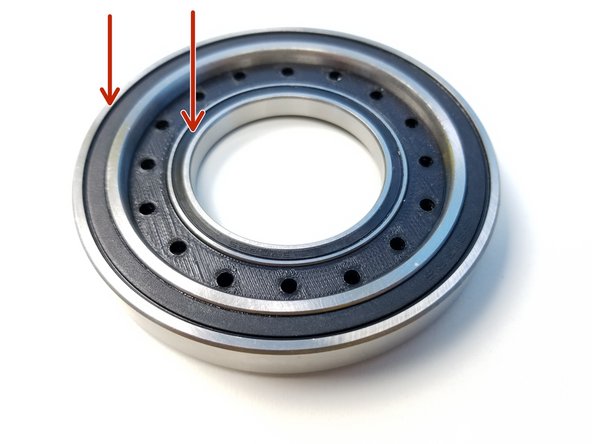
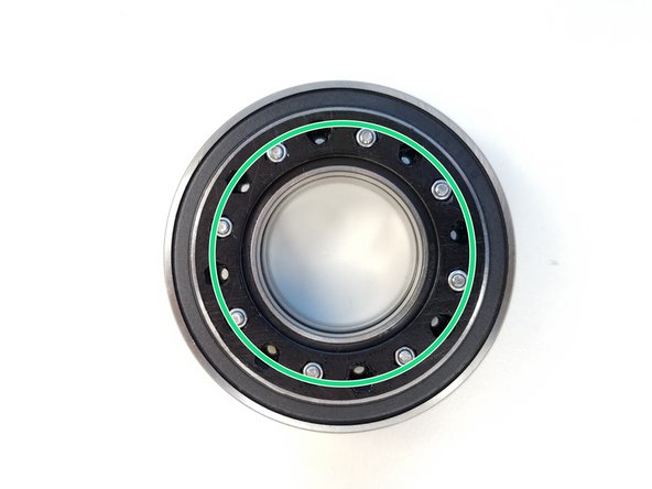
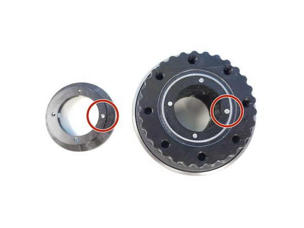
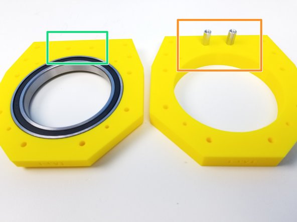
Insert 6813 Bearing and 6708 Bearing in the Nut Insert Half of the Bottom Output Disk
-
NOTE
-
There are 2 sets of Nut Inserts, the one we are concerned about first is the one closer to the center
-
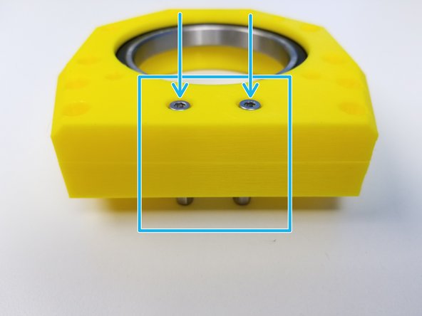
Secure the Bearings by clamping them with Screw Head Half of the Bottom Output Disk using M3x10mm Screws and M3 Nylock Nuts
-
-
-
Prepare the following components:
-
[3D] - 1GB Anchor GB Rotors
-
[3D] - 1PO GB Pulley
-
[3D] - 1GB Input Shafts {Bottom, Eccentric Top}
-
6708 Bearings [40x50x6mm] (x2)
-
M3x35mm Screws (x4)
-
M3 Nylock Nuts (x4)
-
-
-
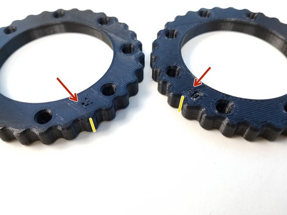
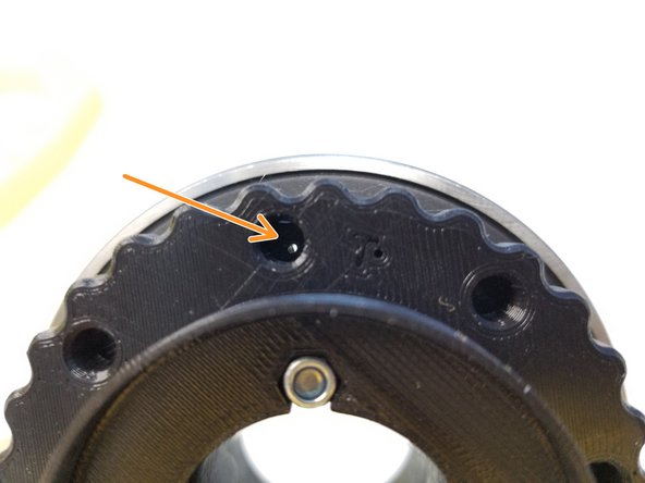
Rotors are labeled "T" for Top and "B" for Bottom
-
Make a sharpie mark on the side of the Rotors along THE HOLE beisde "T" and "B"
-
In other Gearboxes we lined along the T and B label, but NOT THIS TIME
-
New alignment method that's being tested
-
There's a very small hole beside the labels, small enough to get a bobby pin through, when aligned correctly, pin should go all the way through both Rotors
-
Insert 6708 Bearings in to the Rotors
-
-
-
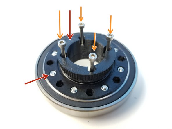
Insert the Input Pulley on the Nut Insert Half side
-
Partially screw in the M3x35mm Screws to secure and Shaft Bottom on the Screw Head Half side
-
Notice that the Eccentric Face of the Shaft Bottom is facing up
-
-
-
Insert "B" Rotor into the Eccentric Cam with "B" Label Facing Outward
-
Repeat the same process with "T" Rotor
-
Align the Eccentric Cam with the Bottom Shaft Cam and partially screw the M3x35mm Screws
-
-
-
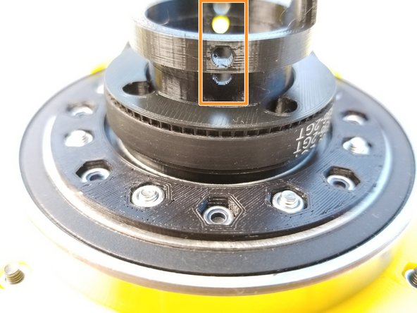
Align the Top Shaft Cam.
-
Just like the Eccentric Cam, the Screw that's touching the bearing should be aligned with the thinner part of the Cam
-
Secure the Top Shaft Cam using the M3 Nylock Nuts and screwing in 'M3x35mm Screws all the way through
-
-
-
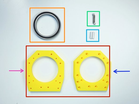
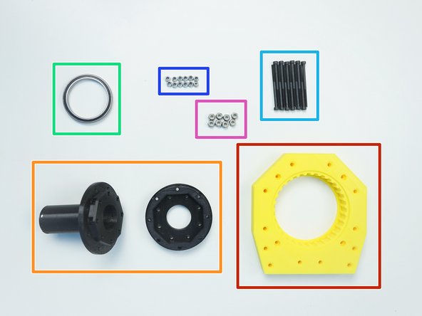
Prepare the following components:
-
[3D] - 1GB Anchor Top Bearing & Spacer
-
6813 Bearing [65x85x10mm] (x1)
-
M4x25mm Screws (x2)
-
M4x20mm Hex Standoff (x2)
-
Note that there are three 3D-printed Anchor Gearbox Housing components, labeled as "1Aa"
-
Anchor Top Bearing is the top component and is chamfered
-
Anchor Top Spacer is the middle component that separates the Anchor Top Bearing and Anchor Gearbox Housing
-
-
-
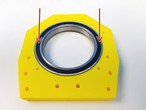
Insert 6813 Bearing into the Anchor Top Bearing
-
Insert the M4 Hex Standoffs to the Anchor Top Spacer
-
Align the Top Spacer and Top Bearing
-
Secure the 2 components using the M4x25mm Screws
-
-
-
Prepare the following components:
-
[3D] - 1GB Anchor GB Housing
-
[3D] - 1GB Output Top Bearing & Disk
-
6708 Bearing [40x50x6mm] (x1)
-
M3x45mm Screws (x12)
-
M3 Nylock Nuts (x12)
-
M4 Nylock Nuts (x8)
-
-
-
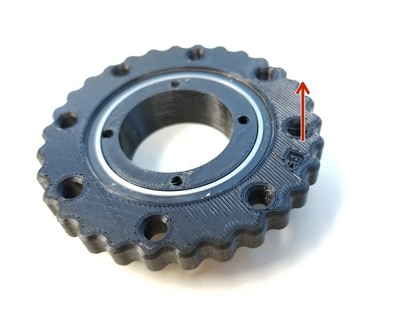
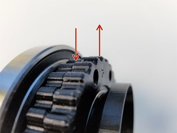
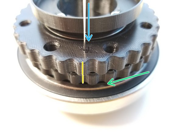
For our new alignment method, Eccentricity is aligned with the T and B label of the Rotors.
-
Notice how the Top Rotor is sticking out yet the Bottom Rotor is not.
-
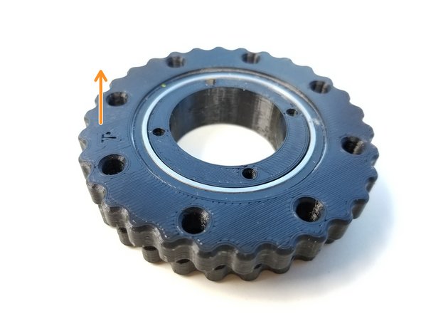
While keeping the Eccentric Shaft and Top Rotor in a fixed position, rotate the Bottom Rotor to a point where you can see the Bottom Alignment Hole
-
Rotate a little more so that the Top and Bottom Alignment Holes are aligned to each other.
-
A pin can be fit right through the 2 alignment holes if done correctly
-
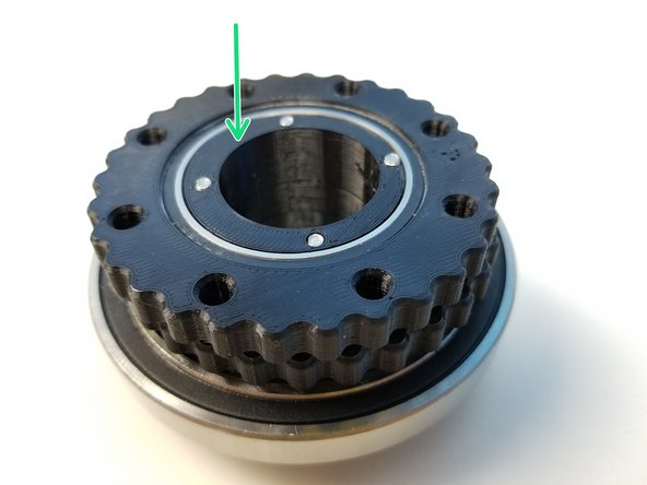
When this is done, you will be able to see that the sharpie marks made from Step 5 aligns vertically too
-
-
-
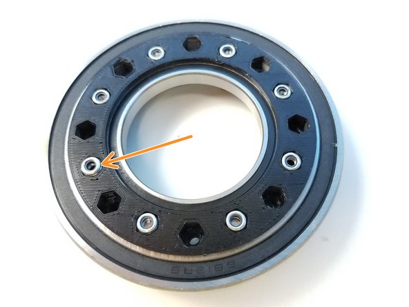
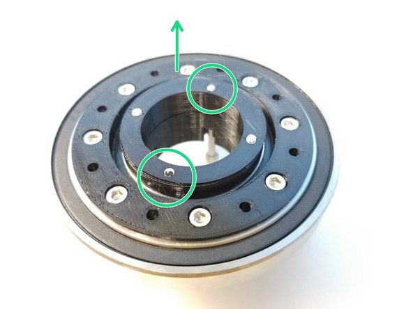
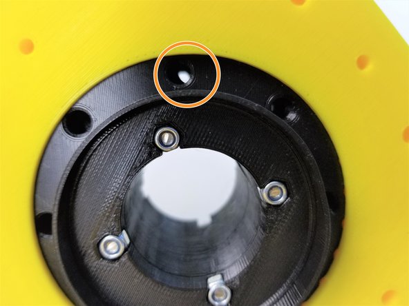
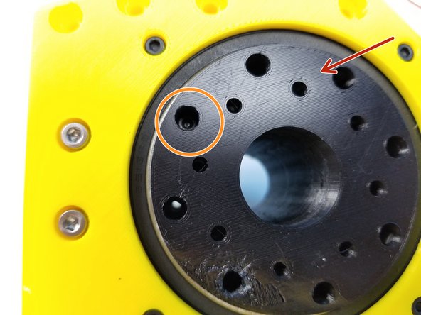
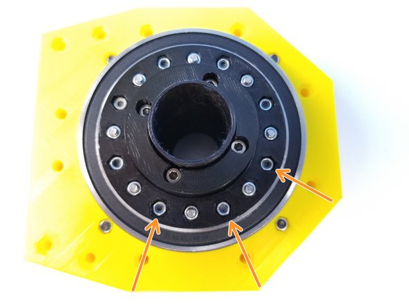
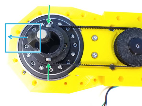
Insert the Rotors in the Anchor Gearbox Housing while maintaining the alignment
-
If aligned correctly, the 8 holes made by the 2 rotors should have equal space
-
Camerac angle could only capture one hole
-
Remove the Alignment Pin once the Rotors are in the Housing
-
-
-
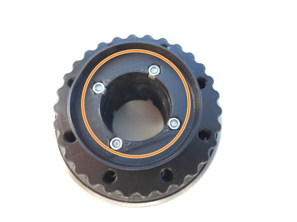
Insert M4 Nylock Nuts into the Output Top Bearing [one with the long tube]
-
Insert 6708 Bearing in Gearbox Shaft Top.
-
Then insert the Top Output Disk into the same bearing
-
-
-
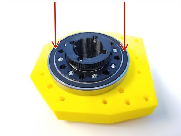
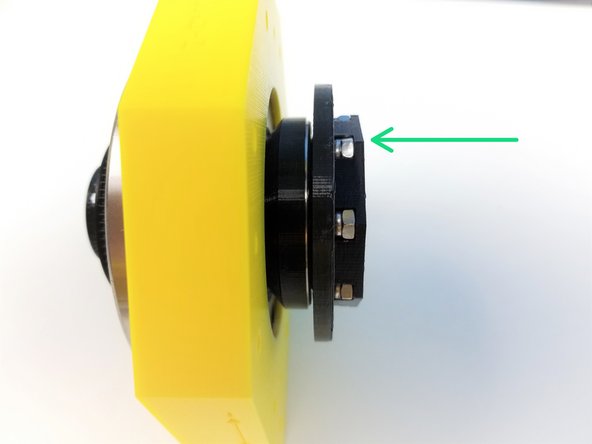
Insert the Top Bearing & Spacer Housing (assembled in Step 10) over the Roller Housing. (Hex standoff should fit right in)
-
Secure these housing components using M3x45mm Screws and M3 Nylock Nuts
-
-
-
Insert the Top Output Disk to the 6813 Bearing
-
Secure the Top and Bottom Output Disks using M3x45mm Screws and M3 Nylock Nuts
-
Verify that you can manually turn the eccentric shaft in the center and that the rotors smoothly turn inside the housing. Tight printing and misaligned rotors can cause the gearbox to jam.
-
-
-
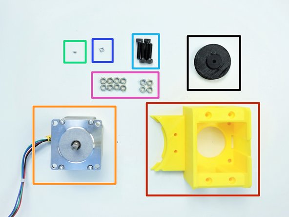
Prepare the following components:
-
[3D] - 1Ab Anchor Motor Holder
-
[3D] - 1PI-pulleyAnchor INPUT-71t
-
NEMA23 56mm Motor
-
M3x4mm Set Screw (x1)
-
M5x25mm Screws (x4)
-
M3 Square Nut (x1)
-
M5 Hex Nuts (x12)
-
-
-
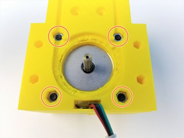
Screw in TWO M5 Hex Nuts in the M5x25mm Screws as spacers
-
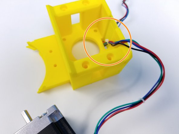
Insert the NEMA 23 Motor to the Motor Holder along with its Cable
-
-
-
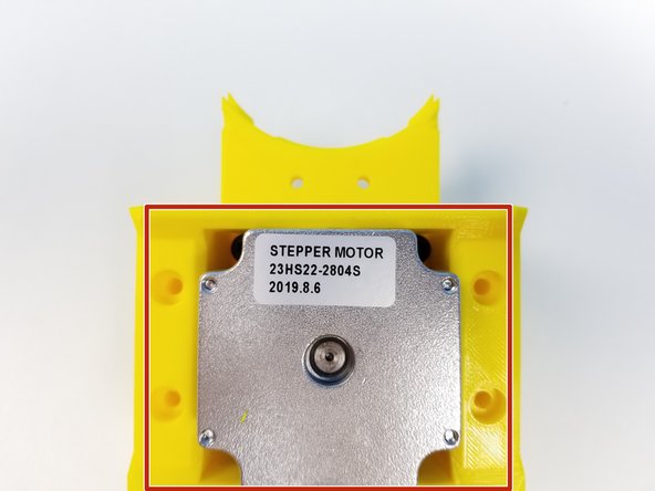
Insert the Motor Body into the Motor Mount
-
Use the M5x25mm Screws and M5 Hex Nuts to Secure the Motor to the Motor Mount
-
-
-
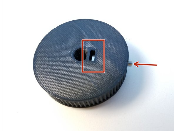
Insert M3 Square Nut in the Pulley and secure it with M3 Set Screw
-
Do Not tighten the screw all the way yet!
-
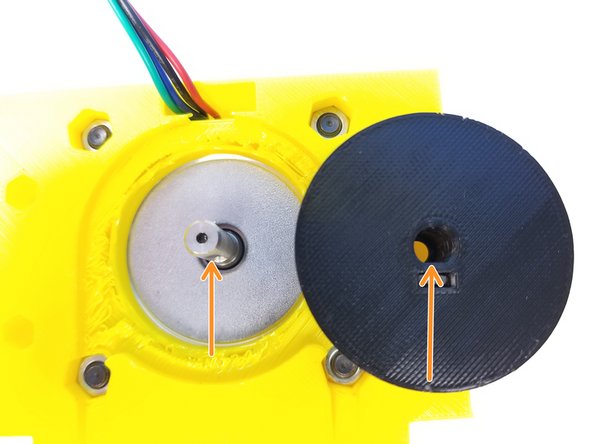
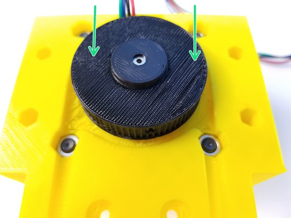
Align the D-Cut on the Motor Shaft and on the Pulley
-
Insert the Pulley and tighten the set screw
-
-
-
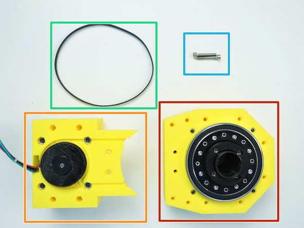
Prepare the following components:
-
Assembled Anchor Gearbox
-
Assembled Anchor Motor Mount
-
Timing Belt GT2-336mm
-
M4x25mm Screws (x2)
-
-
-
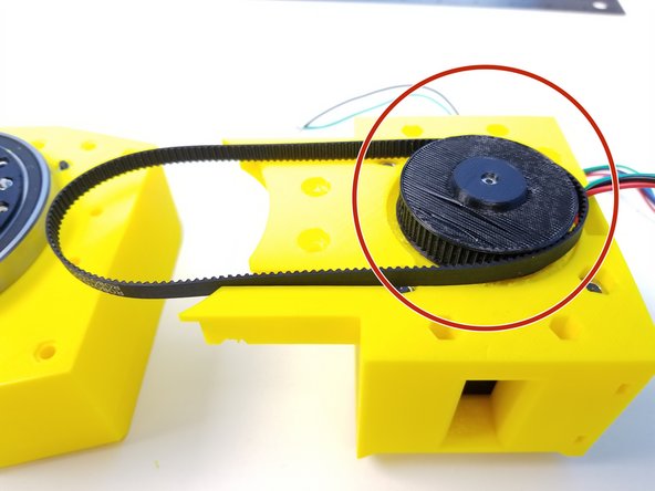
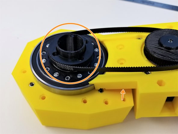
Loop the Timing Belt around the Input Pulley (motor side)
-
Tile the Motor Mount in an angle and loop the Timing Belt on the Ouput Pulley (gearbox side)
-
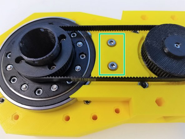
Flatten the Motor Mount and secure its location using M4x25mm Screws (this will tighten the belt)
-
-
-
Prepare the following components:
-
[3D] - 1Ba Anchor Front Bottom
-
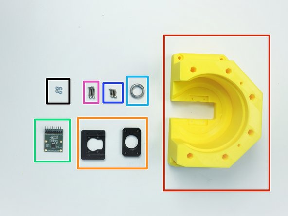
[3D] - AS5147 Sensor Adapter 2 & Anchor Bearing Adapter
-
AS5147 Sensor {right angle header on the chip side}
-
6701 Bearing [12x18x4mm] (x1)
-
M2x6mm Screws (x4)
-
M2x10mm Screws (x4)
-
M2 Hex Nuts (x4)
-
-
-
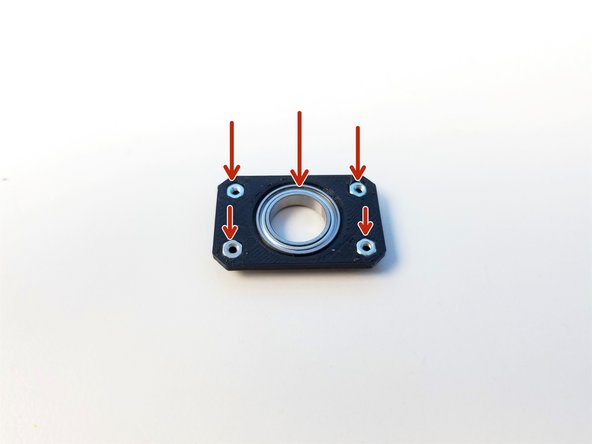
Insert 6701 Bearing and M2 Hex Nuts into the Sensor Bearing Adapter
-
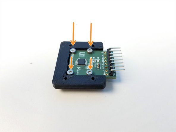
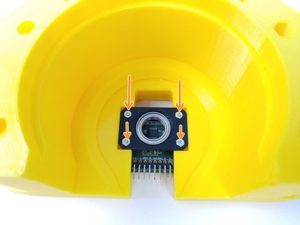
Mount AS5147 Sensor to the Sensor Adapter with the Chip facing up using the M2x6mm Screws
-
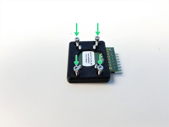
Partially screw in M2x10mm Screws in the Sensor Adapter
-
-
-
Partially screw in M2x10mm Screws into the Anchor Front Bottom
-
Position the Anchor Magnet Bearing so that the bearing is pointing upward and secure it by tightening the M2x10mm Screws all the way
-
-
-
Prepare following components:
-
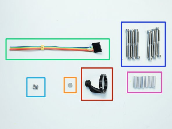
[3D] - 1M Anchor Magnet Holder
-
8x2.5mm Neodymium Magnet
-
6-pin Ribbon Cable F/O - Brown to Blue {sensor 0 Anchor} - [145mm]
-
M3x5mm Screws (x2)
-
M4x45mm Screws (x12)
-
M4x6x20mm Hex Standoffs (x6)
-
-
-
Insert Neodymium Magnet into the Magnet Holder
-
Align the Magnet Holder to the Output Tube
-
Secure the Magnet Holder to the Tube using M3x5mm Screws
-
Align the Magnet Holder so that the "Leg of the Magnet Holder" is pointing to the front center of the Anchor Gearbox
-
-
-
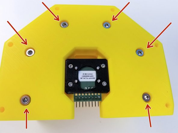
Screw in the Hex Standoffs to the Anchor Front Bottom using M4x45mm Screws
-
Connect the Anchor Sensor Cable to the sensor as shown in the picture
-
BLUE = 3.3V
-
-
-
Align the Anchor Front Bottom to the Anchor Gearbox
-
Make sure the Magnet Holder is aligned with the Bearing!!!
-
Insert the Magnet Holder to the Bearing
-
Secure it using M4x45mm Screws on the Anchor Gearbox
-
-
-
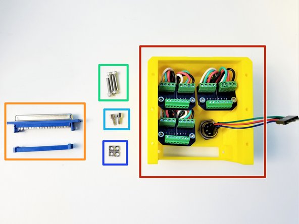
Prepare the following components:
-
[3D] - 1C Anchor Panel Mount
-
Panel Mount PCBs (x3)
-
Aviation GX16-8p Cable M/O - [45mm] (x3)
-
Aviation GX16-8p Cable M/M {other end 4 pin dupont} - [80mm]
-
M3x8mm Screws (x6)
-
-
-
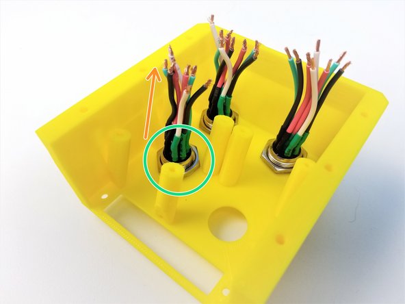
Unscrew all the Nuts and Washers from the Aviation Plugs [43mm]
-
Notice that all 8 pins are soldered to the Plugs
-
Insert the Plugsinto the Back Panel
-
Secure them by screwing in the Nuts and Washers
-
-
-
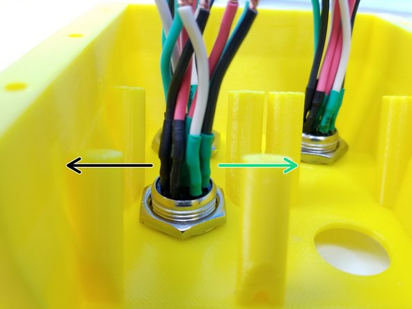
Plug Alignment is very IMPORTANT!
-
Out of 8 pins, 4 pins are soldered then protected with Black Heat Shrinks
-
Other 4 pins are done with Green Heat Shrinks
-
Make sure that Black Set of Wires are on the LEFT
-
When done correctly, alignment aid of the plug should point DOWN
-
Tighten the Plug Nut again
-
Split the Black Set of Wires from the Green Set of Wires
-
-
-
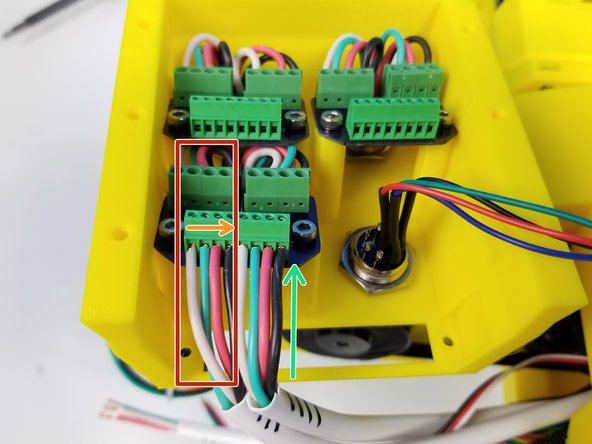
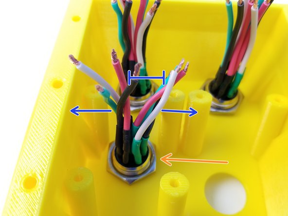
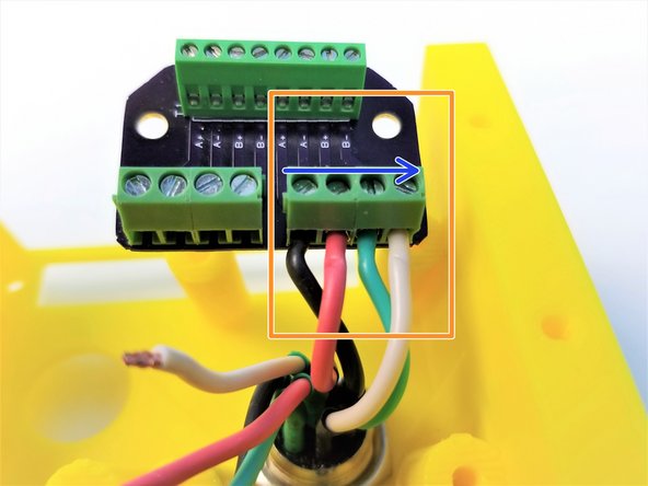
START with the Black Set of Wires of the Bottom Solo Plug
-
Insert the Wires to the Bigger Screw Terminal as shown in the picture
-
From Left (A+) to End (B-)
-
Black -> Red -> Green -> White
-
REPEAT the above process for the Green Set of Wires
-
Do the same for the rest of the Plugs
-
-
-
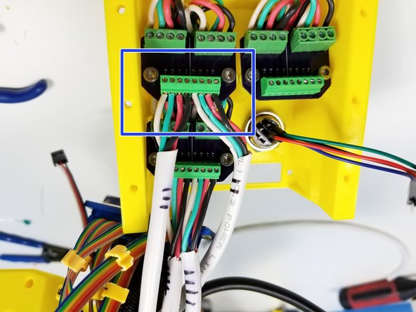
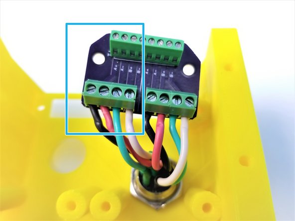
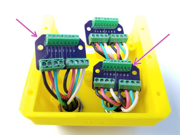
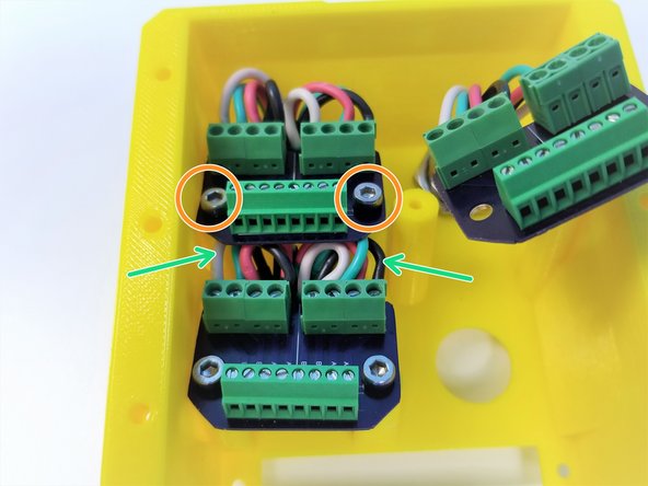
START with the Bottom Solo PCB
-
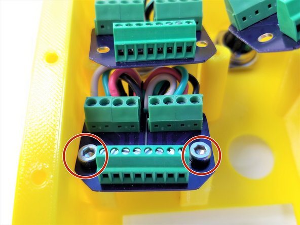
Secure the PCB to the Back Panel using M3x8mm Screws
-
Secure the Top Left PCB next
-
The Wires from the Bottom Solo Plug needs to bend enough for the the Top Left PCB to sit comfortably
-
Finally Top Right PCB
-
Make sure the wires stays in the connectors while bending them
-
Watch out for some of the strands of a wire that could bleed to the neighboring pins!
-
-
-
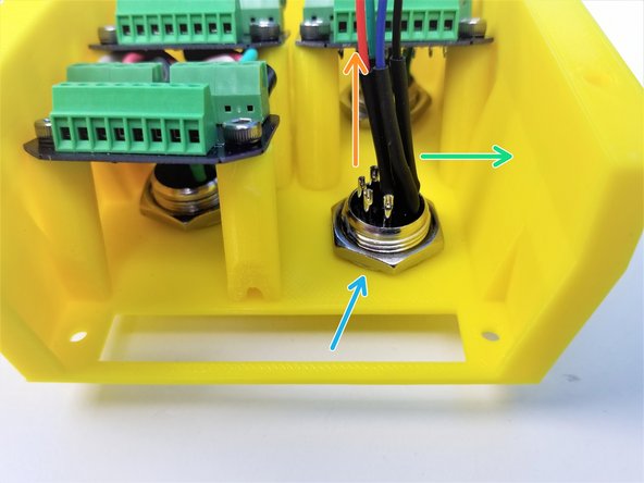
Unscrew all the Nut and Washer from the Aviation Plug [80mm]
-
Notice that there's only 4 wires connected to this plug with 4-pin Male Dupont Connetor
-
Insert the Plug in the Back Panel
-
Align the Plug so that the 4 Wires are on the RIGHT side
-
Tighten the Nut and Washer to secure the Plug
-
When done correctly, alignment aid of the plug should point DOWN
-
-
-
Prepare the following components:
-
Assembled Arm (up to pre-anchor, not shown in the picture)
-
Assembled Anchor (so far)
-
[3D] - 1D Shoulder Mount
-
M4x25mm Screws (x8)
-
M4x45mm Screws (x8)
-
M4 Hex Nuts (x8)
-
-
-
Insert M4 Hex Nuts in the side of Shoulder Mount
-
Align the Shoulder Mount to the Anchor so that "1D" label is facing the FRONT
-
Secure the Shoulder Mount to Anchor using M4x25mm Screws
-
-
-
Shoulder should be at a Neutral Position (middle)
-
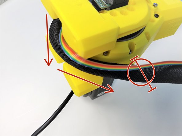
Loop the Braided Cable all the way around the Shoulder Gearbox up to when it reaches 180 degrees
-
Mark this spot on the Braided Cable
-
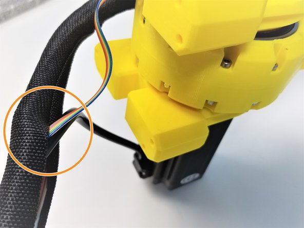
Insert the Shoulder Motor and Sensor Cables in the Braided Cable at the Marked Location
-
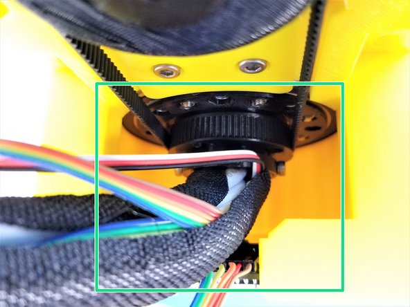
Insert the Braided Cable through the middle hollow tunnel of the Anchor Gearbox
-
Only up to the Marked Location
-
-
-
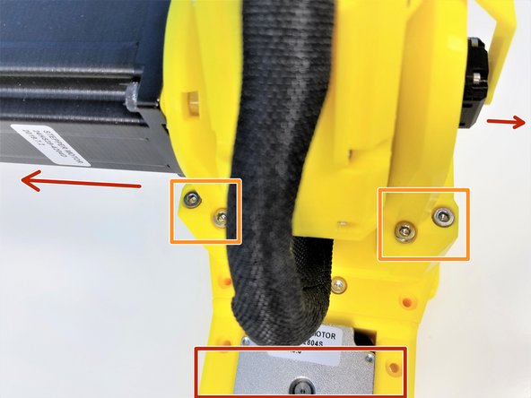
Align the Shoulder Gearbox to the Shoulder Mount (by label on the Mount)
-
Secure the Shoulder using the M4x45mm Screws
-
-
-
Prepare the following components:
-
Assembled Anchor Back Panel
-
D-SUB F-Conn IDC 37p
-
M3x16mm Screws (x4)
-
#4-40x7mm M/F Standoff
-
M3 Square Nuts (x4)
-
-
-
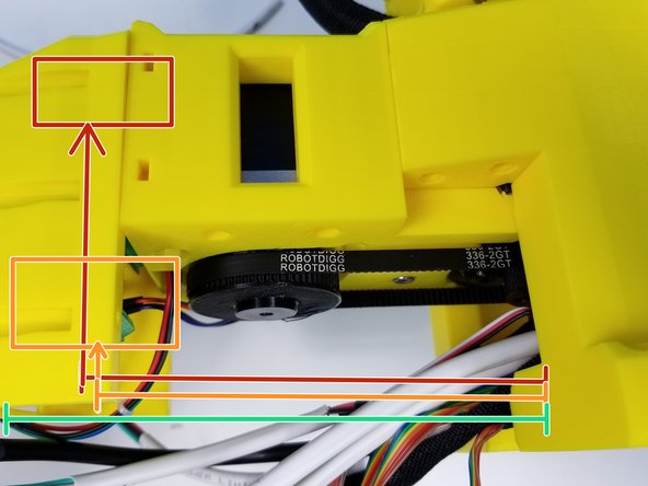
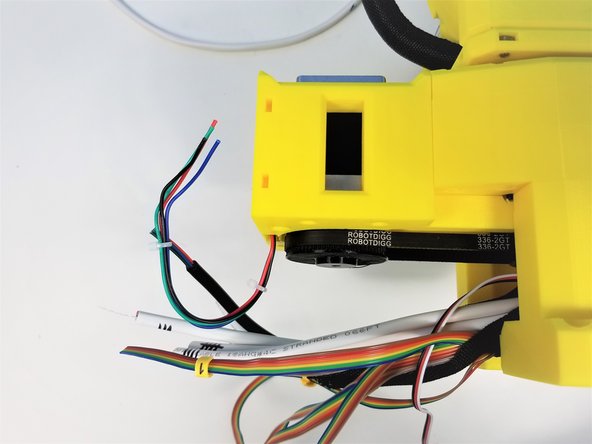
At this point, you will notice that the most of the cables are way longer than the Anchor can hold. '''Therefore we need to cut them to certain length
-
Motor 0 to Motor 3 (4 sets of motor cables)
-
Align each motor cables to this colored line and cut them at the end of the Arrow
-
Motor 4 and 5
-
Sensor Cables
-
-
-
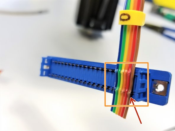
START with the Anchor Sensor Cable
-
Align the Brown wire to the Pin #1. The outside face of the connector is marked with pin numbers to help you get it the right way around.
-
Using the Plier, push the wires into each IDC pins
-
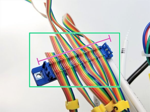
REPEAT for the rest of the Sensor Cables in an incremental arrangment - Anchor[0], Shoulder[1], Elbow[2], Ulna[3], Wrist[4], Hand[5].
-
With 36 wires in total, the last fork at the end will be empty.
-
Once all wires of each cables are in contact with IDC pins, Clamp the IDC Enclosure. Verify that the clamp locks into place on both side to ensure good electric contact.
-
Cut any leftover Cables
-
-
-
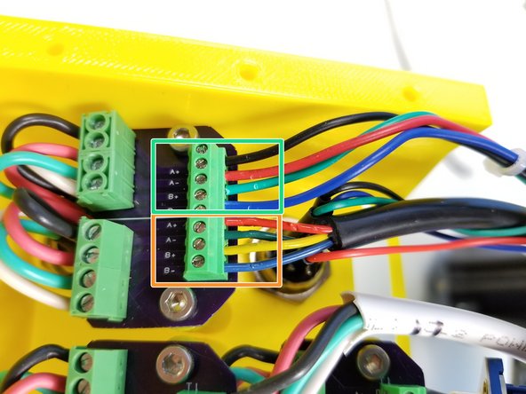
START with the M4 and M5 Cables
-
Connect M5 Cable on the LEFT side
-
From LEFT
-
White -> Green -> Red -> Black
-
REPEAT for M4 Cable on the RIGHT side
-
Do the same for M2 and M3 Cables with M3 Cable on the LEFT side
-
-
-
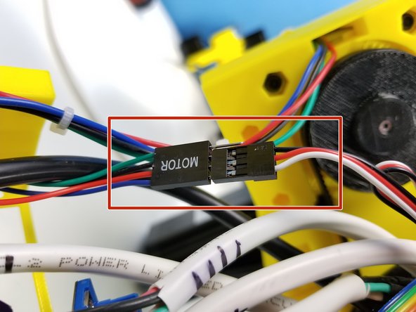
Connect the Tool Cables to each other
-
Black to Black -> Red to Red -> Blue to White
-
Connect M1 Cable
-
According to StepperOnline, from Bottom
-
Blue -> Yellow -> Green -> Red
-
According to Real Life, from Bottom --- DIFFERENT FROM PICTURE
-
Blue -> Green -> Yellow -> Red
-
Connect M0 Cable from Bottom --- Blue -> Green -> Red -> Black
-
-
-
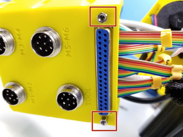
Insert the D-Sub Connector and use #4-40 Standoff to secure it in place.
-
Using M3 Square Nuts and M3x16mm Screws, to secure the Back Panel to the Anchor
-
-
-
Prepare the following components:
-
[3D] - 1Bb AnchorRearBottom
-
M3x16mm Screws (x2)
-
M4x45mm Screws (x16)
-
4 of them are optional
-
M3 Square Nuts (x2)
-
M4 Hex Standoffs (x8)
-
2 of them are optional
-
-
-
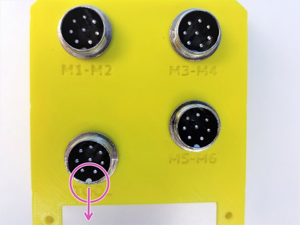
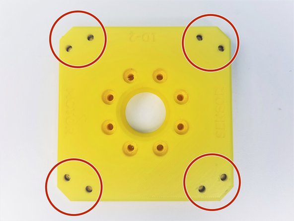
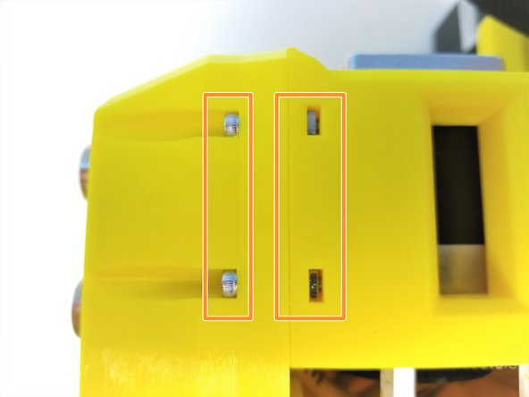
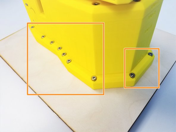
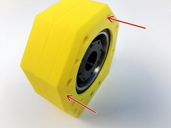
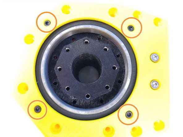
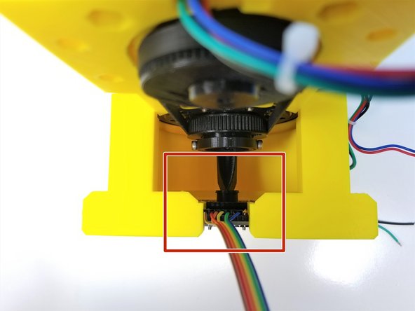
Insert M4 Hex Standoffs in the Anchor Rear Bottom
-
Circled ones are optional
-
Secure that using M4x45mm Screws
-
Circled ones are optional
-
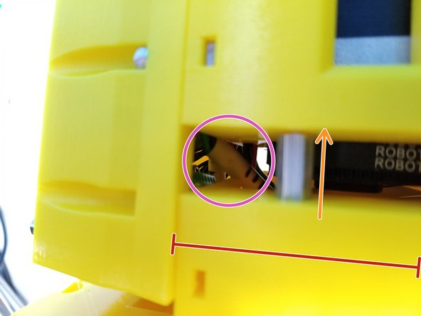
REMEMBER THIS OPENING
-
-
-
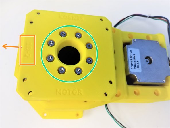
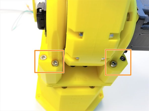
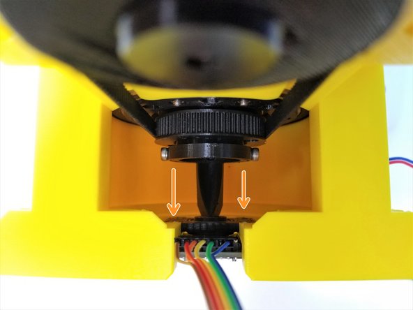
Align the Anchor Rear Bottom to the Anchor
-
Make sure the Cables are fed through the opening (pink reminder from last step)
-
Insert the Hex Standoffs into the Anchor.
-
Secure the 2 components using M4x45mm Screws
-
Optional screw is circled in BLACK
-
You could rotate the Anchor to make an opening for the Screws to go in.
-
-
-
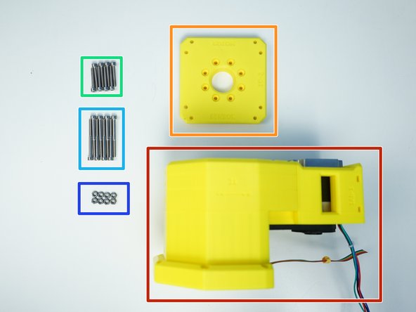
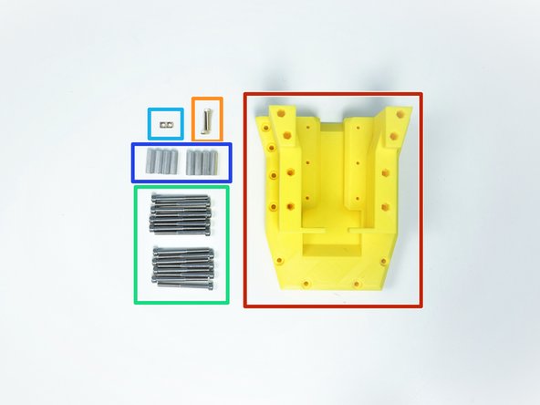
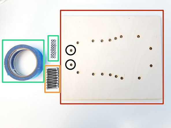
Prepare the following components:
-
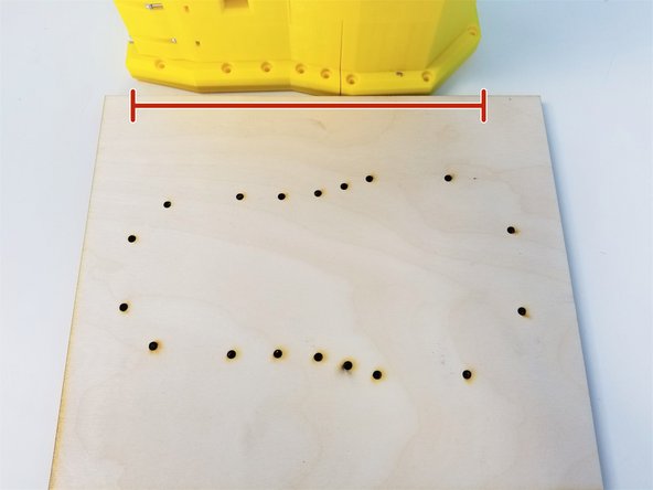
[LSR] - Anchor Mounting Board (3 plates already glued)
-
M4x25mm Screws (x16)
-
M4 Hex Nuts (x16)
-
Tape
-
Circled Hex Nut Inserts are optional, can be ignored.
-
-
-
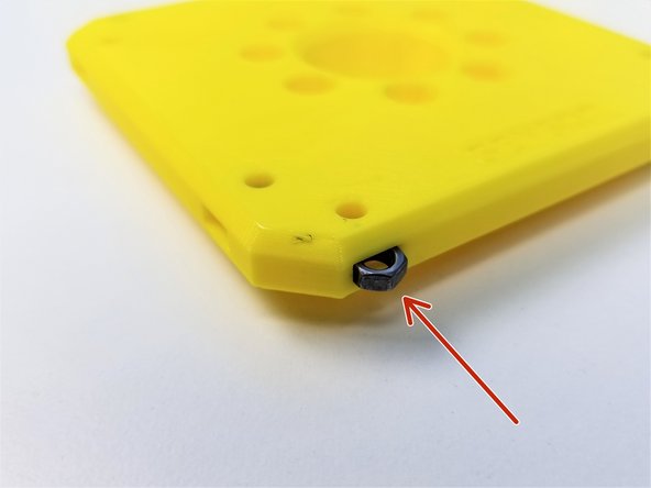
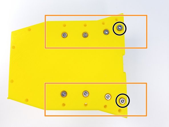
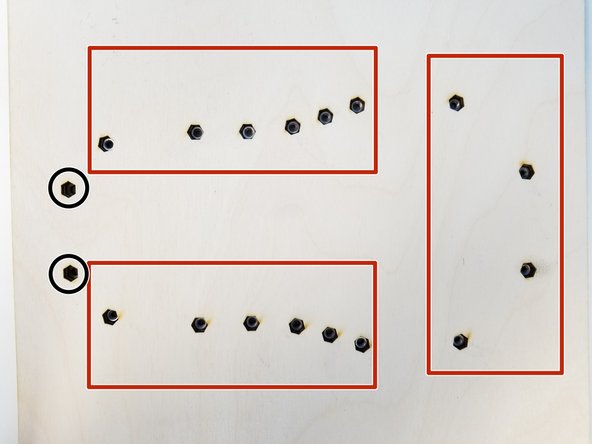
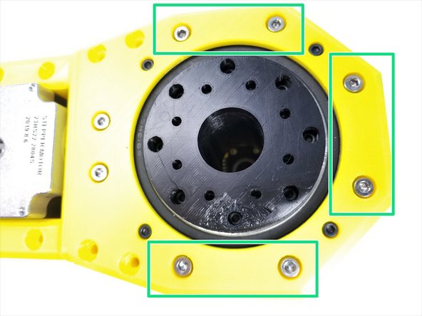
Insert all the M4 Hex Nuts in the Mounting Plate
-
Except for the circled ones
-
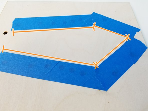
Put the Tape over the Nut inserts
-
-
-
Align the Anchor to the Mounting Plate
-
Secure the Anchor to the Plate using M4x25mm Screws
-
![[3D] - Anchor Components](https://d3t0tbmlie281e.cloudfront.net/igi/mcr/bOKYvZEnuna45Feu.medium)


![[3D] - 1GB Anchor Top Bearing & Spacer](https://d3t0tbmlie281e.cloudfront.net/igi/mcr/TT1LPEAyXovIJTD6.medium)
![Insert M4 Nylock Nuts into the Output Top Bearing [one with the long tube]](https://d3t0tbmlie281e.cloudfront.net/igi/mcr/OTNJv1OLEuDVI6nU.medium)


![Unscrew all the Nuts and Washers from the Aviation Plugs [43mm]](https://d3t0tbmlie281e.cloudfront.net/igi/mcr/euAVxdyEkLDWGbXK.medium)


![Unscrew all the Nut and Washer from the Aviation Plug [80mm]](https://d3t0tbmlie281e.cloudfront.net/igi/mcr/afugD6t3oiPv3kNl.medium)